Gauge wheel tension, Contact drive adjustments, Gauge wheel tension contact drive adjustments – Great Plains 3PYP Operator Manual User Manual
Page 55
Great Plains Manufacturing, Inc.
Adjustments
51
2014-09-09
401-312M
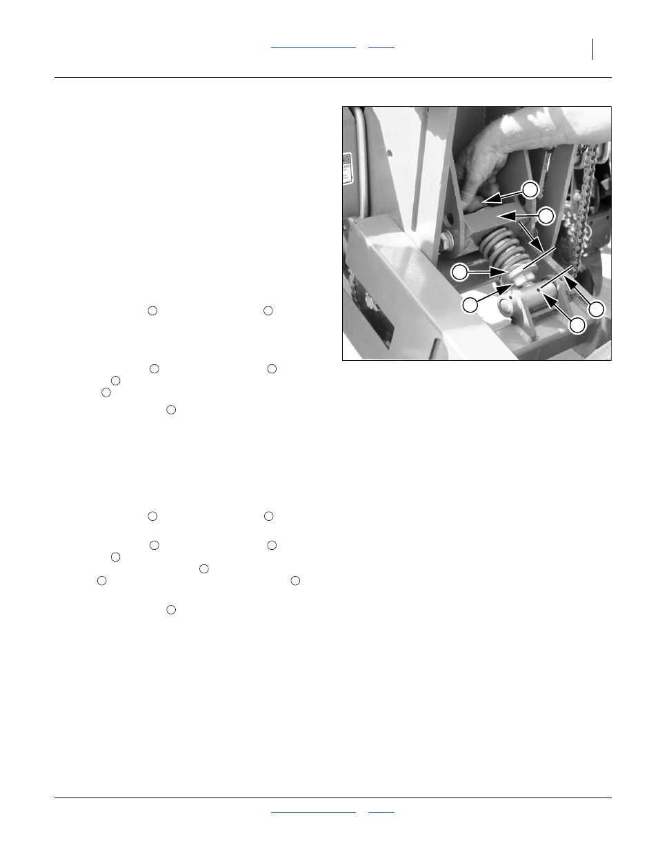
Gauge Wheel Tension
Refer to Figure 52
Before performing this step, the 3PYP center section and
wings must be level and aligned, and the tool bar height
must be set to 26 inches. If these steps have not been
performed, “Frame Height and Leveling” on page 18
and “Wing Leveling” on page 157.
As the gauge wheel tire wears, this adjustment may need
periodic attention.
The planter must be on firm, level ground for this step
(which may be performed when the planter leveling is
done). The planter must be unfolded.
1.
Raise the planter so that the gauge wheels are just
off the ground.
2.
Loosen the nut
above the yoke block
.
3.
Raise or lower the planter so that the base of the tool
bar is 26 inches from the ground.
4.
Using an open-end or adjustable wrench at the
integral hex nut
the link
until the spring is just touching the yoke
block
, with neither gap nor compression.
5.
Tighten the top nut
.
Contact Drive Adjustments
When planting, if the monitor indicates under-seeding,
check for slippage of the gauge wheels. If they are
slipping:
1.
Raise the planter so that the gauge wheels are just
off the ground.
2.
Loosen the nut
above the yoke block
.
3.
Using an open-end or adjustable wrench at the
integral hex nut
the link
to adjust the gauge wheel tension. Using
the base of the link flange
, and the pivot grease
zerk
as a reference, increase this distance
increase down-force on the wheel.
4.
Tighten the top nut
.
Figure 52
Adjusting Gauge Wheel Tension
25258
1
2
4
3
5
6
1
2
4
1
1
2
4
4
6
1