Components, Load cell, dplcm and valves, Electrical system – Great Plains 3PYP Operator Manual User Manual
Page 174
170
3PYP
Great Plains Manufacturing, Inc.
401-312M
2014-09-09
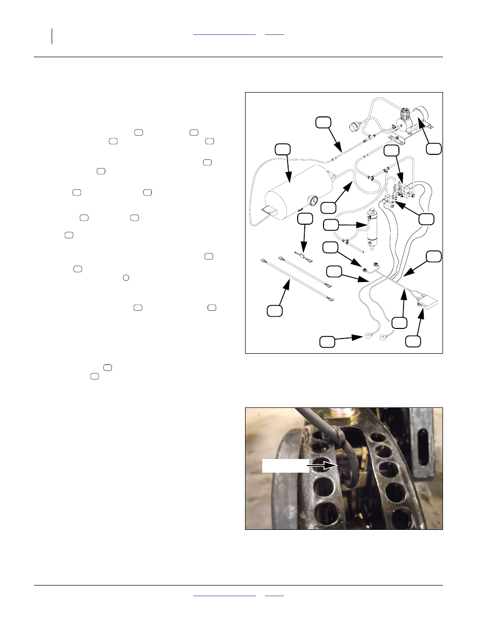
Components
Refer to Figure 173 and Figure 174
The main systems of Row-Pro™ consist of:
1.
An air compressor system:
one 12V air compressor
with air tank
, two
extension cables
2.
A load sensing system:
DPLCM (Down Pressure Load Cell Module)
and
the load cells
.
3.
An adjusting system:
valves
Load Cell, DPLCM and Valves
The DPLCM
and valves
are mounted together on
a plate and are connected to the DICKEY-john
®
wiring
harness
.
The load cell located on the center most opener is
attached to the DICKEY-john
®
wiring harness at
.
Four leads
on the DICKEY-john
®
wiring harness
connect to the valve sets
. There is one pair (one air
intake, one exhaust) for each valve.
Note: For single row planters:
There is one load cell
and one valve set
per
each opener section located at mid section.
Note: For twin row planters:
There are two load cells and two valve sets per
each opener section located on the long center row
unit of the section.
The wiring harness
connects to the planter at
connector ends
®
system.
Electrical System
Place the compressor as close to the tractor battery as
possible using the least amount of electrical connections
as possible to minimize voltage drop. The battery
connection is equipped with one large 60 amp spade
fuse (automotive type).
Note: If your tractor has an on-board engine driven
compressor capable of 150 psi, it can be used
instead of the one supplied with the planter. Hook
the on-board compressor to the air tank with lines
provided.
13
15
16
18
17
12
19
14
11
23
11
22
20
24
Figure 173
Row-Pro™ Components
31878
11
12
22
15
13
1
15
16
17
18
4
13
16
Figure 174
Load Cell Location (Opener)
32089
load cell