Locking pins – Great Plains 3PYP Operator Manual User Manual
Page 28
24
3PYP
Great Plains Manufacturing, Inc.
401-312M
2014-09-09
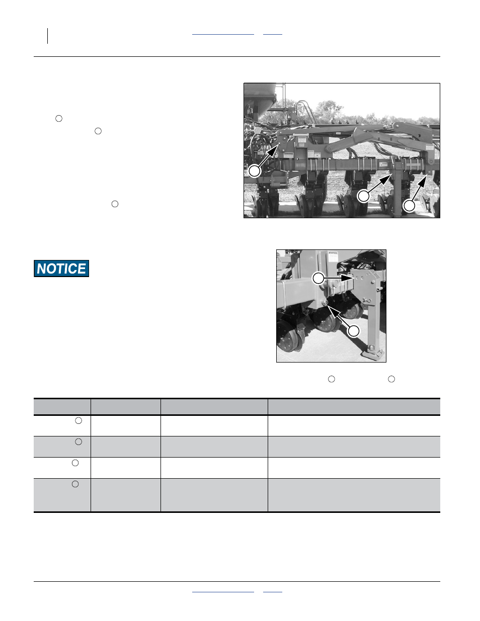
Locking Pins
Refer to Figure 19
Each wing has two removable pins, stored in the parking
stand
when not in use:
• Wing Lock Pin
Used to connect the wing tool bar to the center section
tool bar during planting operations, and keep the wing
tool bar at the same height as the mainframe tool bar.
When this pin is installed at the coupling, the outer
wing is either rigid, or can flex (depending on the
planter “flex” configuration)
• Wing Flex Lock Pin
Required to stabilize pivot during folding and
unfolding. Used during planting to prevent wing flex.
The following table summarizes pin use.
The
INNER pins must be IN
and the
OUTER pins must be OUT
during folding and unfolding,
or machine damage will result.
Figure 19
Wing Lock Pin Locations
25248
1
2
3
1
2
3
Pin
Location
During
Comments
Wing Lock
Stowed
• Planter Folded
Must be removed from coupling during folding
and unfolding or machine damage will result.
Wing Lock
Tool bar Coupling
• Planting
Must be removed from coupling during folding
and unfolding or machine damage will result.
Flex Lock
Stowed
• Planting
Must be present in pivot during folding and
unfolding or machine damage will result.
Flex Lock
Wing Arm Pivot
• Folding/Unfolding
• At all times on “Flex Lock”
planters
Must be present in pivot during folding and
unfolding or machine damage will result.
Figure 20
Wing Lock
& Pin Storage
25247
2
1
1
2
2
2
3
3