Steering setup – Great Plains 3PYP Operator Manual User Manual
Page 154
150
3PYP
Great Plains Manufacturing, Inc.
401-312M
2014-09-09
If you do not have one of the brands and models listed on
this page, consult your Great Plains dealer. The list of
supported tractors, and available sensor mounting
brackets, is planned for expansion.
At time of publication, this 3PYP steering system was not
expected to become compatible with tracked or
articulated tractors.
Seed cart steering is hydraulically controlled to match
steering of the tractor based on one of the following:
• the extension of a linear displacement sensor at the
tractor steering gear
• the value of the steering angle signal on the CANbus,
• the value of the signal as transmitted from the steering
sensor.
You will find one of the following three major
subassemblies installed on your tractor:
1.
the electronic steering module connected to the
tractor’s implement CAN network
2.
the electronic steering module connected directly to
the tractor, factory installed steering angle sensor
3.
a tractor steering sensor, with brand-model-specific
brackets, which detects tractor wheel pointing.
Sensor installation is normally completed by the
Great Plains dealer prior to delivery. If it was not,
obtain the Pre-Delivery Manual (part number
401-312Q) from the dealer. Only the Pre-Delivery
manual includes tractor steering sensor installation
instructions.
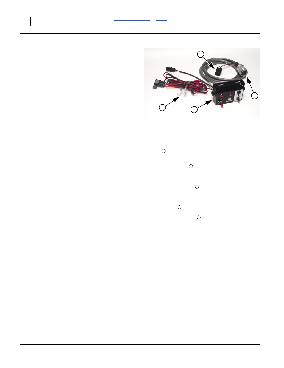
Refer to Figure 144
Do the following setup to the cab steering switch
console
which controls operation and calibration of the
steering system:
Mount the switch box
in any convenient location that
allows observation of fault indications, and does not
obstruct safe operation of the tractor.
Route the main harness
to the hitch, where it mates
with the Steering ECU harness.
Connect the steering module or tractor sensor lead to the
3-pin connector
.
Connect the power leads
to a 12Vdc source (red +,
black -).
Steering Setup
Perform a steering calibration, per “Steering
Calibration” on page 151.
Figure 144
Steering Switch Box & Harness
31783
1
2
3
4
1
1
2
3
4