Transmig vaf4 – Tweco VAF4 Transmig User Manual
Page 58
TRANSMIG VAF4
INSTALLATION, OPERATION AND SETUP
3-40
Manual 0-5231
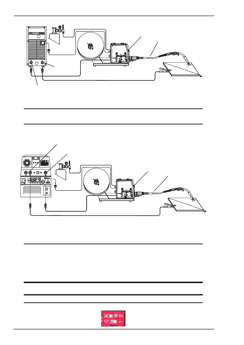
Connection of VAF4 to Transmig 400i for Welding with Gas Shielded MIG Wire
Art # A-11345
Mig Torch
VAF4 Wirefeeder
Gas
14-pin Control Cable
Electrode Lead*
Work Lead*
Positive Welding Terminal (+)
Negative Welding Terminal (-)
*These leads may need to be reversed when using flux cored welding wire.
Contact the welding wire manufacturer for more details.
Figure 3-37(b) Setup for Wirefeeder with MIG (GMAW) Welding
NOTE
Interconnection Assembly 19 pin to 14 pin, 8m (W4016000) required.
NOTE
Refer to Subsection 3.09 for wirefeeder DIP switch setting required for Transmig 400i power source.
Connection of VAF4 to Engine Drive for Welding with Gas Shielded MIG Wire
Art # A-11346
Gas
Electrode Lead*
Work Lead*
14-pin Control Cable
VAF4 Wirefeeder
Positive Welding Terminal (+)
Negative Welding Terminal (-)
*These leads may need to be reversed when using flux cored welding wire.
Contact the welding wire manufacturer for more details.
Mig Torch
Figure 3-37(c) Setup for Wirefeeder with MIG (GMAW) Welding
NOTE
Interconnection Assembly 19 pin to 14 pin, 8m (W4016000) required for connection to an MPM8/ 255
or MPM8/ 270 engine-driven welding power source.
An additional adaptor cable W4016001 is required in conjunction with a 19 pin to 14 pin interconnec-
tion cable assy (Refer to Table 2-3 for further detail) for connection to MPM12/ 400 or MPM20/ 500
engine-driven welding power source.
WARNING
There are dangerous voltage and power levels inside this product. Turn OFF wirefeeder and disconnect
from the power source before removing cover from wirefeeder.
NOTE
Refer to Subsection 3.24 and set internal DIP switch SIL_1 # 2 to ON.