06 front panel controls, indicators and features, Front panel controls, indicators and features -3, Transmig vaf4 – Tweco VAF4 Transmig User Manual
Page 21: Amps, Wirespeed)
TRANSMIG VAF4
Manual 0-5231
3-3
INSTALLATION, OPERATION AND SETUP
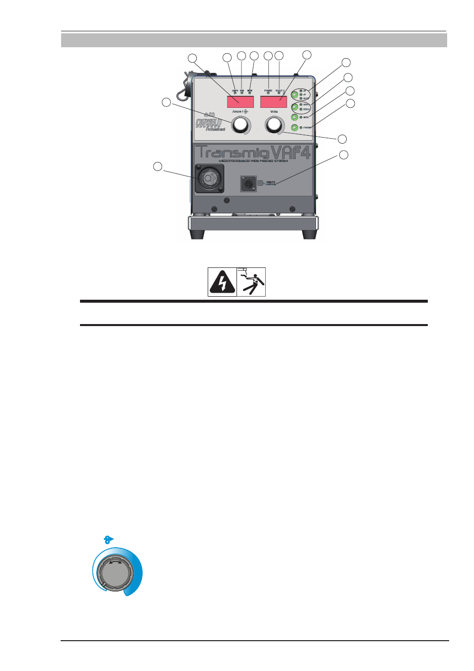
3.06 Front Panel Controls, Indicators and Features
1 2
3
7
5
4
8
6
9
10
11
12
13
15
14
Art # A-11255_AB
Figure 3-1 Front Panel View
WARNING
DO NOT TOUCH the electrode wire while it is being fed through the system. The electrode wire will be
at welding voltage potential.
1. POWER Indicator
The red power indicator will be illuminated when the Wirefeeder is turned ON and indicates the presence of power.
2. FAULT Indicator
The yellow fault indicator will be illuminated when any faults are detected. Should a fault condition occur refer to
Subsections 3.30, 3.31, 4.05 or 4.08 for further information.
If the Fault indicator is flashing whilst welding refer to Subsection 3.31 as the motor overload protection is active.
3. AMPS Indicator
The red AMPS indicator will be illuminated when the Left Display displays the amperage.
4. IPM Indicator
The red IPM indicator will be illuminated when the Left Display displays WFS in Inches Per Minute (IPM).
5. MPM Indicator
The red MPM indicator will be illuminated when the Left Display displays WFS in Metres Per Minute (MPM).
6. Left Knob
Left Knob
Amps /
(Wirespeed)
The control knob adjusts Wire Feed Speed (WFS) (which in turn adjusts the output current by turning the amount
of MIG wire delivered to the welding arc). The optimum WFS required is dependent on the type of welding ap-
plication. The value may also be adjusted while a weld is in progress – if this occurs, the left display will briefly