07 rear panel controls and features, Rear panel controls and features -8, Transmig vaf4 – Tweco VAF4 Transmig User Manual
Page 26
TRANSMIG VAF4
INSTALLATION, OPERATION AND SETUP
3-8
Manual 0-5231
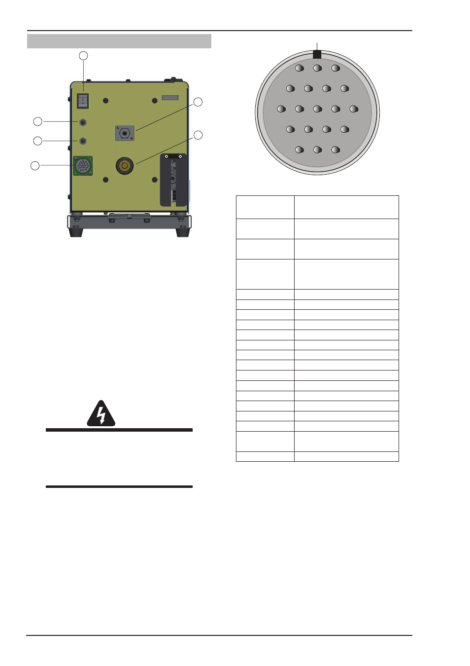
3.07 Rear Panel Controls and Features
16
17
18
19
20
21
Art# A-11256
Figure 3-3 Rear Panel View
16. ON/ OFF Switch
Press this switch to turn ON or turn OFF the Wirefeeder.
17. Gas Inlet
Gas inlet allows to connect the shield gas.
18. Control Cable Socket
The control cable connects to the power source at this
19-pin amphenol connector. It contains the signals re-
quired to allow the welding power source and the wire
feeder to work together as a system.
WARNING
The protective earth ground (pin G) of the
control cable is established ONLY when the
power source is properly grounded. See the
power source owner’s manual for proper
grounding methods.
19. Welding Cable Connector
This connector allows to connect welding cable with
Wirefeeder. Please make sure that it is secured firmly,
or it will heat and generate arc.
20. 4A Circuit Breaker
This circuit breaker protects the wirefeeder from electri-
cal faults on the 115VAC circuit. In the event of a fault
occuring this circuit breaker will trip (pop out). A short
cooling period must be allowed before an attempt is
made to reset it by pressing it back in. Refer to Subsec-
tion 4.08 for further details.
Keyway
A
M
L
K
U
N
B
C
P
V
T
J
H
S
R
D
E
F
G
Figure 3-4 Pin Identification
Control Cable
Pin
Function
A
Contactor + (Shorted to B
to turn ON Power Source)
B
Contactor- (Shorted to A to
turn ON Power Source)
C
Voltage Feedback ( 1
Volt is 10 Arc Volts)
D
Not Used
E
115 VAC Hot
F
42VAC and 115VAC Neutral
G
Protective Earth Ground
H
Remote Control Maximum
J
Remote Control Signal
K
Not Used
L
Power Source Common
M
Arc Established (= +15 VDC)
N
Power Source Select Line
P
Not Used
R
Not Used
S
42VAC Live Wire
T
Not Used
U
Current Feedback (1 Volt
is 100 Arc Amps)
V
Not Used
Table 3-2 Control Cable Pin Functions
21. 8A Circuit Breaker
This circuit breaker protects the wirefeeder from electri-
cal faults on the 42VAC circuit. In the event of a fault
occuring this circuit breaker will trip (pop out). A short
cooling period must be allowed before an attempt is
made to reset it by pressing it back in. Refer to Subsec-
tion 4.08 for further details.