Hmc-410 – Tweco HMC-410 User Manual
Page 71
HMC-410
May 5, 2005
5-9
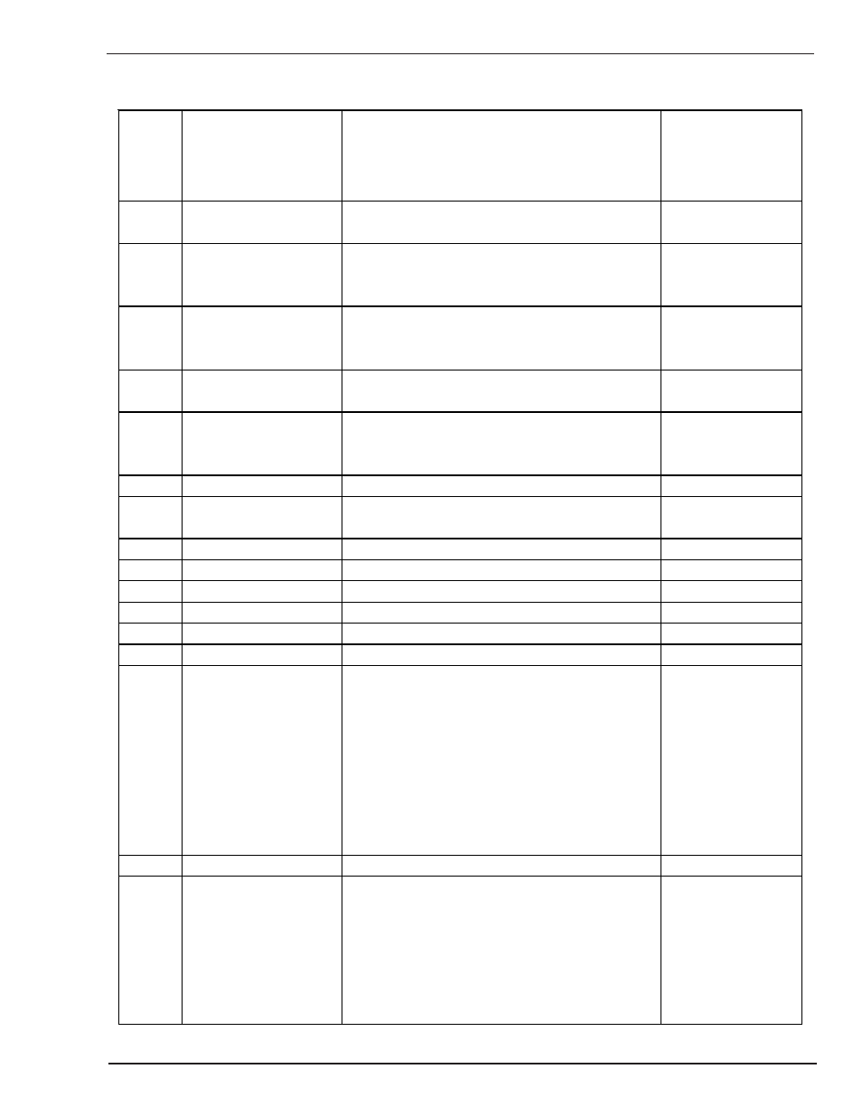
Switch Position
1=OPEN, 0=CLOSED
Test No.
Name
Description
SSSSSSSS
12345678
44
Display Remote Stop
Display B will display the state of the Remote
00011010
Stop Switch. 0 = Pressed, 1 = Not Pressed
45
Display Aux Start/Stop
Display B will display the state of the
01011010
Auxiliary Start/Stop Switch. 0 = Pressed, 1 =
Not Pressed
46
Display Arc Established Display B will display the state of Arc
00111010
Established. 1 = Arc Established,
0 = Arc Not Established
47
Display Ground Fault
Display B will display the state of the Ground
01111010
Fault. 0 = Ground Fault, 1 = No Ground Fault
48
Display Ground Fault
Display B will display the state of the Ground
00000110
(Latched)
Fault Latch. 0 = Ground Fault has occurred,
1 = No Ground Fault has occurred.
49
RELAY 0 TEST
Contactor Relay Closed.
01000110
50
RELAY 1 TEST
Gas Valve Relay Closed. P1-7 will have 24
00100110
VAC Hi on it.
51
RELAY 2 TEST
Fixture Relay #1 Closed.
01100110
52
RELAY 3 TEST
Fixture Relay #2 Closed.
00010110
53
RELAY 4 TEST
Error Relay Closed.
01010110
54
RELAY 5 TEST
00110110
55
RELAY 6 TEST
01110110
56
IL2 TEST
00001110
57
RAM TEST
The RAM test will perform a diagnostic test
01001110
on internal RAM. The top display will display a
memory location (selected by the top encoder)
and the middle display will display a value
written to RAM (selected by the middle
encoder). The bottom display will show the
data at that memory location; if the RAM is
working correctly, that value will be the same
as the number in the middle display.
58
No Test
59
EEPROM
This selection will configure the schedules
01101110
60
Initialization
and softswitches to factory defaults. This
00011110
selection will show the test number in the top
display, and count numbers in the middle
display (normally 1 to 255, with some jumping
around towards the end). When the middle
display clears, the initialization is complete.
5.06 Built In Test (BIT) Definition (continued as Table 5-1c)