Section 4: operation, 01 system configuration, Section 4 – Tweco HMC-410 User Manual
Page 41: Operation -1, 01 system configuration -1, Hmc-410
HMC-410
July 27, 2005
3-1
SECTION 3:
INSTALLATION
3.01 Location
When selecting an installation site, take care to avoid
locations exposed to high ambient temperature, high
humidity, dust, or corrosive liquids or fumes. Moisture
condenses on electrical parts, causing corrosion or short
circuits. Dirt on parts retains moisture and increases wear
on moving parts.
3.02 Assembly
Components of this system are completely assembled at
the factory. When received at the job site, it will be
necessary to refer to instruction manuals and/or
instruction sheets for details on setup of the system in
which the controller is to be used. See TIPs supplied with
the manual for information on the feedhead, wire supply,
and cabling.
3.03 Electrical Connections
See the System Outline drawing (170921) in the Appendix
chapter of this manual for details.
CAUTION:
Make sure all connections are tight; otherwise,
arcing or overheating could result.
1. Make the proper welding cable connections between
the power source and wire feeder and between the
power source and work connection.
2. Connect the power source control cable to the control
panel “PS” amphenol connector.
3. Connect a control cable between the wire feeder and
the control panel “FDR” amphenol connector.
4. Connect the remote pendant (if used) to the control
panel “REM” amphenol connector.
5. Connect a control cable (if used) between the PLC or
similar controller and the control panel “AUX”
amphenol connector.
6. Make the proper gas line connection from the gas
supply to the wire feeder gas valve (if gas will be used).
7. Attach the welding gun to the wire feeder.
8. Connect the welding gun control leads to the wire
feeder gun switch terminals located on the front of
the feeder.
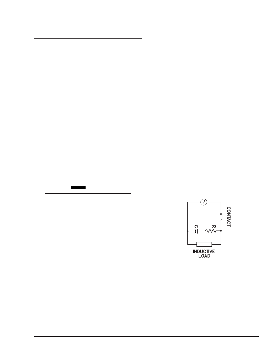
3.04 Load Suppression
The HMC-410 provides three relays on the auxiliary
amphenol connector for customer use, the ratings of these
relays are listed in the Description of Equipment chapter
of this manual. Proper load suppression will extend relay
life as well as minimize electromagnetic interference. Due
to the unique nature and requirements of each load, it is
required that the customer provide load suppression. The
following guidelines and Figure 3-1 are provided to help
with the selection of components.
Device Selection for AC Operation
Resistor — 0.5 to 1 Ohm per contact volts
Capacitor—0.5 to 1 Microfarad per contact amps
Use AC type capacitors (non-polarized) with a breakdown
voltage of 200 to 300 V. Always test your selection in
actual use.
Example:
An inductive load requiring 120 V AC, 1 Amp; the resistor
should be between 60 and 120 ohms, and the capacitor
between 0.5 and 1 microfarad with a 200 to 300 volt rating.
Art # A-04367
Figure 3-1: Load Suppression Schematic