Light module wire harness locations, 23" bar, 5" bar – SoundOff Signal Magnum LED User Manual
Page 11: 8" bar, 48" bar, 3" bar, 5" bar 73.0" bar, Emg2000 magnum™ led lightbar
IMPORTANT INFORMATION:
Warning devices are strictly regulated and governed by Federal, State and Municipal ordinances. These devices shall be used ONLY on approved vehicles. It is the sole responsibility of the user of these devices to ensure compliance.
To review our Limited Warranty Statement & Return Policy for this or any SoundOff Signal product, visit our website at
www.soundoffsignal.com/sales-support.
If you have questions regarding this product, contact
Technical Services, Monday - Friday, 8 a.m. to 5 p.m. at 1.800338.7337 (press #4 to skip the automated message).
Questions or comments that do not require immediate attention may be emailed to
SUPERIOR CUSTOMER RELATIONSHIPS. SMARTLY DESIGNED LIGHTING & ELECTRONIC SOLUTIONS.
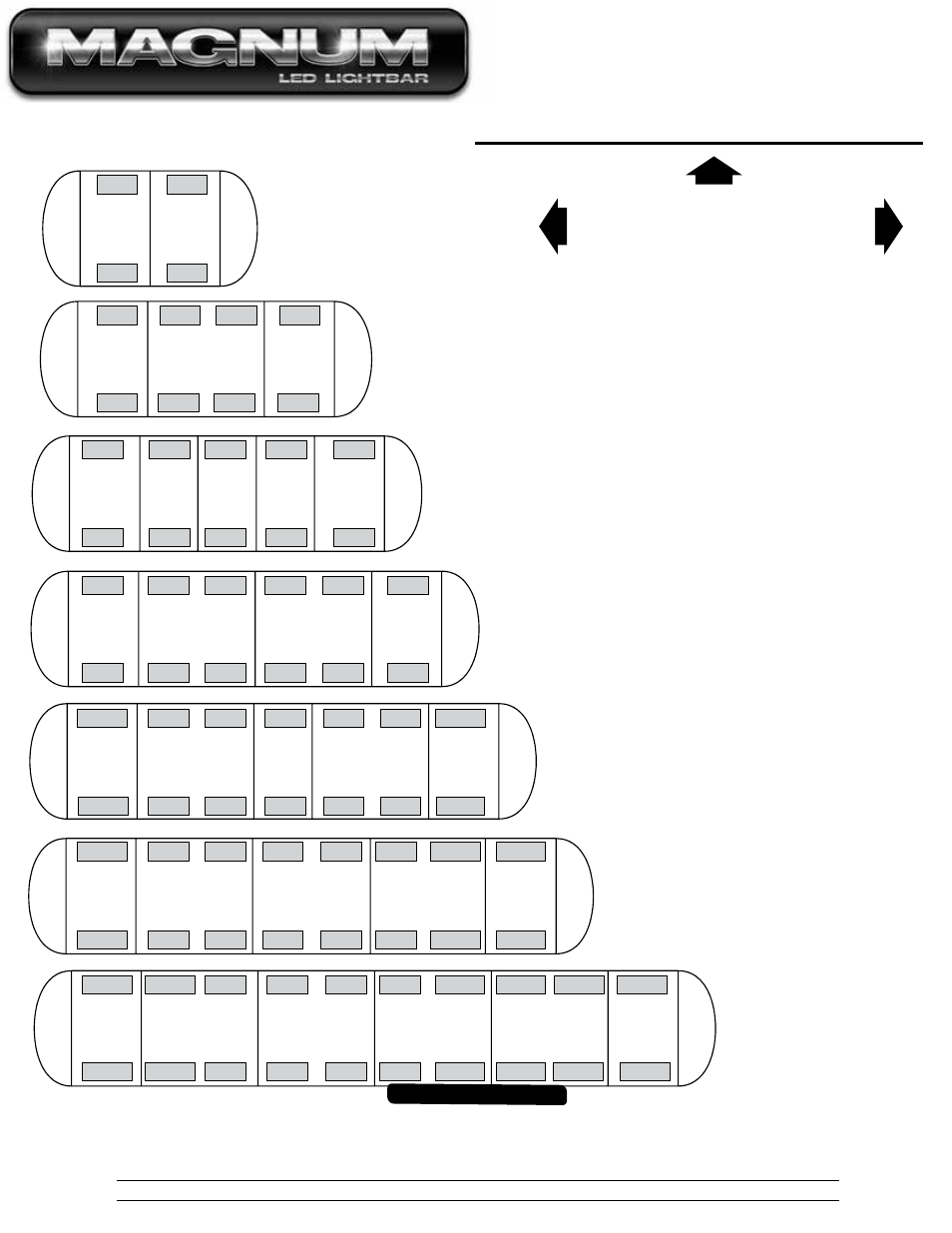
FRONT
DRIVER
SIDE
PASSENGER
SIDE
LIGHT MODULE WIRE HARNESS LOCATIONS
GREEN
11
RED
12
GREEN
RED
31
32
23" BAR
GREEN
11
RED
12
RED
13
GREEN
14
GREEN
31
RED
32
RED
33
GREEN
34
35.5" BAR
BLUE
11
BLUE
31
41.8" BAR
GREEN
12
GREEN
32
RED
13
RED
33
GREEN
14
GREEN
34
BLUE
15
BLUE
35
48" BAR
BLUE
11
BLUE
31
GREEN
12
GREEN
32
RED
13
RED
33
RED
14
RED
34
GREEN
15
GREEN
35
BLUE
16
BLUE
36
54.3" BAR
BLUE
11
YELLOW
31
YELLOW
11
31
BLUE
12
BLUE
32
GREEN
13
GREEN
33
RED
14
RED
34
GREEN
15
GREEN
35
BLUE
16
BLUE
36
BLUE
17
YELLOW
37
YELLOW
BLUE
11
YELLOW
11
BLUE
12
GREEN
13
RED
14
RED
15
GREEN
16
BLUE
17
BLUE
BLUE
18
YELLOW
BLUE
YELLOW
BLUE
GREEN
RED
RED
GREEN
BLUE
BLUE
BLUE
YELLOW
31
32
33
34
35
36
37
38
BLUE
11
11
12
BLUE
13
GREEN
14
RED
15
RED
16
BLUE
17
GREEN
BLUE
18
BLUE
BLUE
19
YELLOW
BLUE
20
BLUE
BLUE
GREEN
RED
RED
BLUE
GREEN
BLUE
BLUE
31
32
33
34
35
36
37
38
BLUE
YELLOW
39
BLUE
40
60.5" BAR
73.0" BAR
REPLACEMENT OF INBOARD AND CORNER MODULES:
1. Disconnect main power.
2. Remove top cover by removing screws.
3. Locate module and remove mounting screws. Pull or
slide module from lightbar.
4. Remove connector from rear of module by carefully pulling connector
body from back of module.
5. Push module connector into replacement module ensuring locking
latch is seated properly or connector is fully seated.
6. Replace module and hardware that fasten module to base
extrusion.
7. Restore power to bar and test new module to ensure functionality.
8. Replace top cover of bar with screws removed in step 2.
• Colors shown indicate wire colors on wire harness.
• Inboard modules: color/color (eg. red/red) wires go to
front inboard modules, color/white (eg red/white) go to
back inboard modules.
• Corner modules: orange/black wires go to front, red/
black wires go to back.
• Split center modules: follow previous front/back color
locations, and connect red wires from each side to the
split board "IN" connectors. The "OUT" / "TO MODULE"
connector goes to the short adapter wire harness and
then the module.
• Takedown modules: black/red wires with white or
black label.
• Alley modules: black/red wires with gray label
#EMG2000 MAGNUM™ LED Lightbar
YELLOW
BLUE
YELLOW