Mounting the controller, Din rail mounting option – Banner PresencePLUS Pro—PRO Camera User Manual
Page 15
P/N 68368 rev. B
9
01/04
Installation Manual
Hardware Installation
Banner Engineering Corp. • Minneapolis, MN USA
www.bannerengineering.com • Tel: 763.544.3164
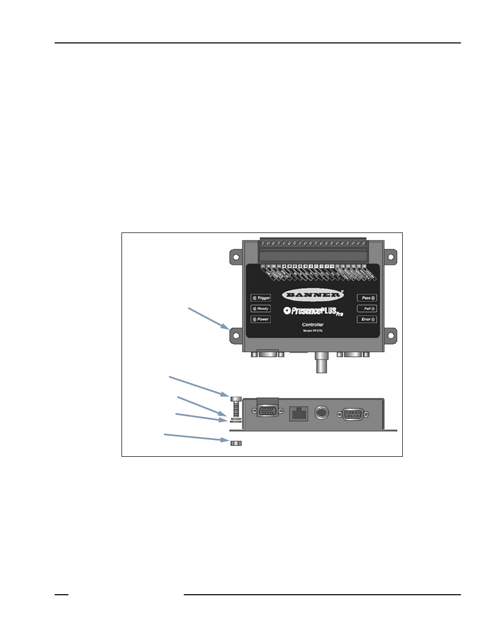
Mounting the Controller
Mount the controller to a Banner controller mounting bracket (See
on page 35) or to a flat
surface using its four mounting flanges, as shown below.
Allow a minimum of 75 mm (3
"
) of clearance for cable bend relief.
The following mounting hardware is supplied with the controller:
• Four M5 x 0.8 x 14 mm socket head cap screws
• Four M5 x 0.8 hex nuts
• Four split lock washers
• Four flat washers
• Short-arm hex key wrench
-----------------------------------
For dimension details, see
---------------------------------------------------------------
Controller Mounting Example
DIN Rail Mounting Option
Mount the controller to a DIN rail using Banner controller mounting bracket SMBPPDH for flat mounting or
SMBPPDE for edge mounting. Hardware for fastening the bracket to the controller is included with the bracket.
Mounting Flange
Cap Screw
Lock Washer
Flat Washer
Hex Nut