Metrohm 793 IC Sample Preparation Module User Manual
Page 16
2 Installation
793 IC Sample Prep Module/ 8.793.1003 Instructions for Use
12
The inlet and outlet capillaries mounted on the SP Module A are then
connected up. Proceed as follows:
1 Insert SP Module A
x Place SP Module A 21
21
21
21 on the floor of the inner chamber of
the 733 Separation Center.
2 Connect SP Module A
x Remove the plastic stopper from opening 41
41
41
41 or 43
43
43
43 on the
733 IC Separation Center and push cable 23
23
23
23 mounted on the
SP Module A 21
21
21
21 through the opening.
x Connect cable 23
23
23
23 to connection 17
17
17
17 “Actuator“ of the 793 IC
Sample Prep Module (see Fig. 5).
3 Connect sample line to 793 SP Module A
x Screw inlet capillary 24
24
24
24 marked with "Sample in" at SP Module
A connection 22
22
22
22 (see Fig. 6) onto connection “5” of injection
valve B using a 6.2744.010 compression fitting.
4 Connect SP Module A to valve A (Preconcentration
column)
x Screw outlet capillary 29
29
29
29 marked with “Sample out” onto
connection “1” of injection valve A using a 6.2744.010 com-
pression fitting.
x Please note, that the preconcentration column at valve A has
to be rinsed in counterflow when switched from “Fill” to “In-
ject”.
1
3
2
24
24
24
24
27
27
27
27
28
28
28
28
29
29
29
29
25
25
25
25
26
26
26
26
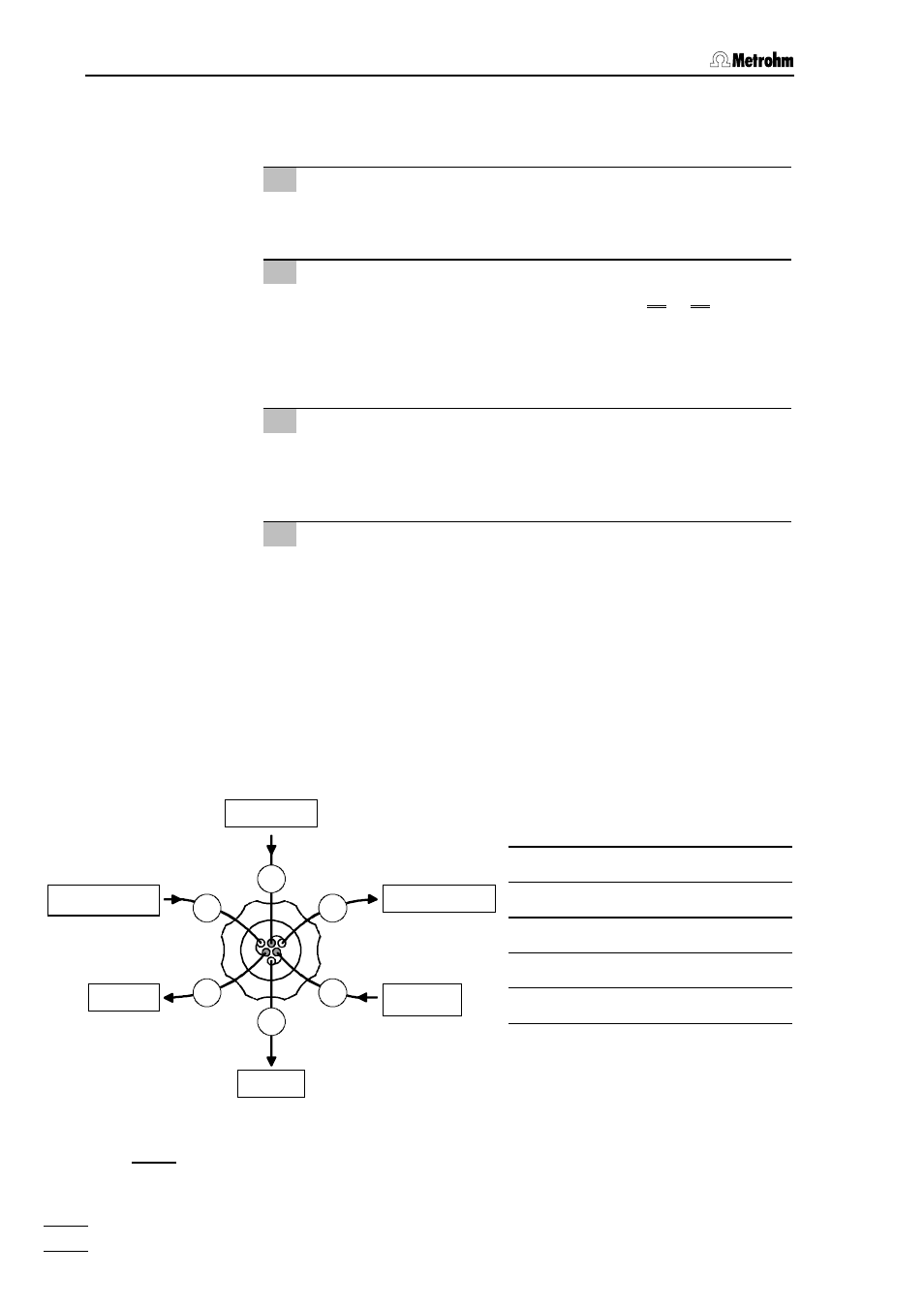
Fig. 6:
Connections at SP Module A
24
24
24
24 Inlet capillary for sample
25
25
25
25 Inlet capillary for acid
26
26
26
26 Outlet capillary for acid
27
27
27
27 Outlet capillary for H
2
O
28
28
28
28 Inlet capillary for H
2
O
29
29
29
29 Outlet capillary for sample
H
2
O
Regenerant
Waste
Sample in
Sample out
Waste