Installation instructions – Brandmotion 9002-9504-V2 User Manual
Page 8
INSTALLATION INSTRUCTIONS
9503 and 9504 Instructions 7-10-13.doc
8
of
12
950
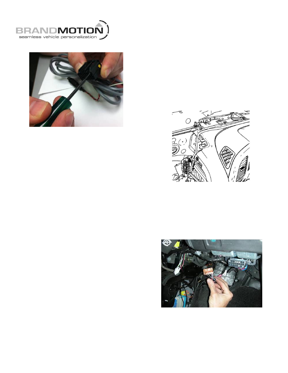
FIGURE 29
To remove any extra wires, insert the Delphi
Terminal Tool or small screwdriver into the hook lever
on face of the mirror harness connector and press the
selected pin out through the back of connector.
56. Insert the Gray/Orange wire into the connector. Use
cavity 2 for Kit 9504 with comp/temp or cavity 7 for
Kit 9503. Figure 28.
Note: If a wire exists in this cavity, remove and
isolate with electrical tape. Figure 29.
57. If your vehicle is NOT equipped with an auto
dimming mirror and wires are NOT present in
cavities 9, 13, or 8, you must purchase a 9002-
6105 harness separately from Brandmotion and
connect it as follows:
a. Insert Brown reverse terminal (if 6105 harness has a
gray jacket) or Green reverse wire (if 6105 harness
has a black jacket) from the 6105 harness into cavity
9.
b. Insert Green ignition terminal (if 6105 harness has a
gray jacket) or Red ignition wire (if 6105 harness has
a black jacket) from 6105 harness into cavity 13.
c. Insert White ground terminal (if 6105 harness has a
gray jacket) or Black ground wire (if 6105 harness
has a black jacket) from 6105 harness into cavity 8.
d. Splice Brown reverse wire (if 6105 harness has a gray
jacket) or Green reverse wire (if 6105 harness has a
black jacket) at the RCA connector end of the 6105
harness to the Green reverse wire of the supplied
foam wrapped Mirror Harness.
e. Splice Green ignition wire (if 6105 harness has a gray
jacket) or Red ignition wire (if 6105 harness has a
black jacket) at the RCA connector end of the 6105
harness to the Pink ignition wire of the supplied foam
wrapped Mirror Harness.
f. Splice White ground wire (if 6105 harness has a gray
jacket) or Black ground wire (if 6105 harness has a
black jacket) at the RCA connector end of the 6105
harness to the Black ground wire of the supplied foam
wrapped Mirror Harness.
58. Press down on the TPA device to lock the wires into
the mirror harness 16-pin connector. NOTE: The
TPA will not lock flush if terminal(s) are not seated
completely; use Delphi Terminal Tool 12094429 or a
small flat blade watch repair screwdriver to press
the terminals all the way into their respective
cavities and press down on the TPA device to lock.
Figure 28.
59. Route the other end of the supplied mirror Harness
down the Driver’s Side Instrument Panel near the A-
pillar. Figure 30.
FIGURE 30
Connect Supplied Mirror Harness to
Power, Reverse, and Ground
NOTE: Follow Steps 60-66 only if you located Reverse
signal at the C10/X10 or C11/X11 M-BEC Connector. If
Reverse was not present, proceed to Step 67.
60. Remove C12/ X12 Connector (Brown) from the M-
BEC. Figure 31.
FIGURE 31
61. Remove the TPA from the C12/ X12 Connector.
Figure 17.
62. Connect the Pink wire from the supplied Mirror
Harness to C12/ X12 Cavity 7. Figure 28. NOTE:
Pickups with cooled seats require a Denali Jumper
Harness, Brandmotion kit number 9002-6005,
available separately.