Mirror harness pinout, Plug supplied mirror harness into mirror connector, Pin mirror connector – Brandmotion 9002-9504-V2 User Manual
Page 7
"#$%&''&%"(#!"#$%)*+%"(#$
9503 and 9504 Instructions 7-10-13.doc
7
of
12
950
FIGURE 27
51. Remove two Roof Console Screws (2). Figure 27.
Pull down the Roof Console Assembly (3) to disengage
the retainer clips (4). Figure 27.
Plug Supplied Mirror Harness into Mirror
Connector
Mirror Harness Pinout
PIN
#
WIRE
COLOR
FUNCTION
Kit
9002-9503
Kit
9002-9504
1
Gray/
Dk Blue
N/A
Video (+)
2
Gray/
Orange
N/A
Video (-)
3 - 5
N/A
N/A
N/A
6
Gray/
Dk Blue
Video (+)
N/A
6
Varies
N/A
Outside
Temperature (+)
7
Gray/
Orange
Video (-)
N/A
7
Varies
N/A
Outside
Temperature (-)
8
Black
Ground
Ground
9
Varies
Reverse Signal
12V+
Reverse
Signal 12V+
10
N/A
N/A
N/A
11
Varies
OnStar Keypad
Output
OnStar
Keypad Output
12
Varies
OnStar Keypad
Power
OnStar
Keypad Power
13
Pink
Ignition
Controlled
12V+
Ignition
Controlled
12V+
14
Varies
OnStar LED
Green
OnStar LED
Green
15
Varies
OnStar LED Red
OnStar LED
Red
16
N/A
N/A
N/A
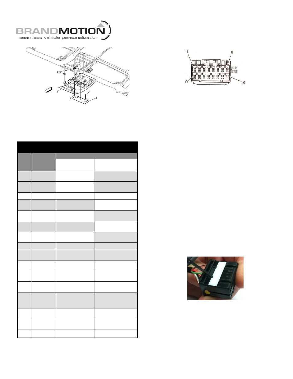
16-pin Mirror Connector
Note: Cavities are numbered on the back side of
the mirror connector. Additionally, Brandmotion
identifies Cavity 1 with a white mark.
52. Use a digital multimeter or computer safe test light
to test cavity 9 for Reverse signal. Set parking
brake, start vehicle, and shift into Reverse.
A. If Reverse signal is present in cavity 9,
proceed to Step 53.
B. If Reverse signal is NOT present in cavity
9, check for wires in cavities 13 and 8. If
cavities 13 and 8 do NOT contain wires,
proceed to Step 57.
C. If Reverse signal is NOT present in cavity 9
and cavities 13 and 8 contain wires, remove
and isolate any pin present in cavity 9. Figure 29.
Then, plug the 16-pin terminal of the supplied
Green 6’ Wire into cavity 9. Next, splice the
opposite end of supplied Green 6’ Wire into the
Green wire on the supplied Mirror Harness using
solder and cover with heat shrink tubing
(recommended) or using T-taps as an alternate
method. Proceed to Step 53.
53. Disengage Terminal Position Assurance (TPA) device
(rectangular white tab) on mirror connector. Use
Delphi Terminal Tool 12094429 or a small flat blade
watch repair screwdriver to pry up the notches in
the TPA. The tab will only lift about 1/10
”
. Figure 28.
FIGURE 28
54.
Insert the Gray/Dark-Blue wire of the mirror harness
into the mirror harness connector. Use cavity 1 for
Kit 9504 with comp/temp or cavity 6 for Kit 9503.
Figure 28.
Note: If a wire exists in this cavity, remove and
isolate with electrical tape. Figure 29.