2 understanding the i/o image – Rockwell Automation RECOMM-DNET DeviceNet Adapter for use with DPI AC Drives User Manual
Page 56
6-2
DeviceNet Adapter for use with DPI AC Drives
6.2
Understanding the I/O Image
The DeviceNet specification requires that the terms input and
output be defined from scanner’s point of view.
Output I/O is data that is output from the scanner and consumed by
the DeviceNet adapter.
Input I/O is status data that is produced by the adapter and
consumed as input by the scanner. The I/O image table will vary
based on the following:
• Size (either 16-bit or 32-bit) of the Reference/Feedback word and
Datalink words used by the drive.
• Configuration of DPI I/O Config (13) in the adapter. If all I/O is not
enabled, the image table is truncated. The image table always
uses consecutive words starting at word 0.
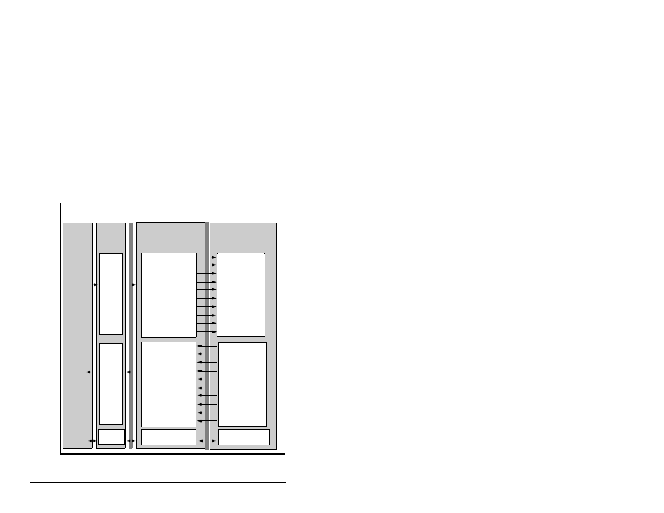
Figure 6.1 illustrates an example of an I/O image with 16-bit words.
Figure 6.1 – Sample I/O Image with All I/O Enabled
Controller
Scanner
Module
SP600 Drive
DeviceNet
DPI
Output
Image
(Write)
Input
Image
(Read)
Message
Handler
Message
Buffer
Message
Handler
0 Logic Status
1 Feedback
2 Datalink Out A1
3 Datalink Out A2
4 Datalink Out B1
5 Datalink Out B2
6 Datalink Out C1
7 Datalink Out C2
8 Datalink Out D1
9 Datalink Out D2
0 Logic Command
1 Reference
2 Datalink In A1
3 Datalink In A2
4 Datalink In B1
5 Datalink In B2
6 Datalink In C1
7 Datalink In C2
8 Datalink In D1
9 Datalink In D2
Logic Command
Reference
Data In A1
Data In A2
Data In B1
Data In B2
Data In C1
Data In C2
Data In D1
Data In D2
Logic Status
Feedback
Data Out A1
Data Out A2
Data Out B1
Data Out B2
Data Out C1
Data Out C2
Data Out D1
Data Out D2
Word and I/O