2 setting an adapter to transmit peer-to-peer data – Rockwell Automation RECOMM-DNET DeviceNet Adapter for use with DPI AC Drives User Manual
Page 34
4-10
DeviceNet Adapter for use with DPI AC Drives
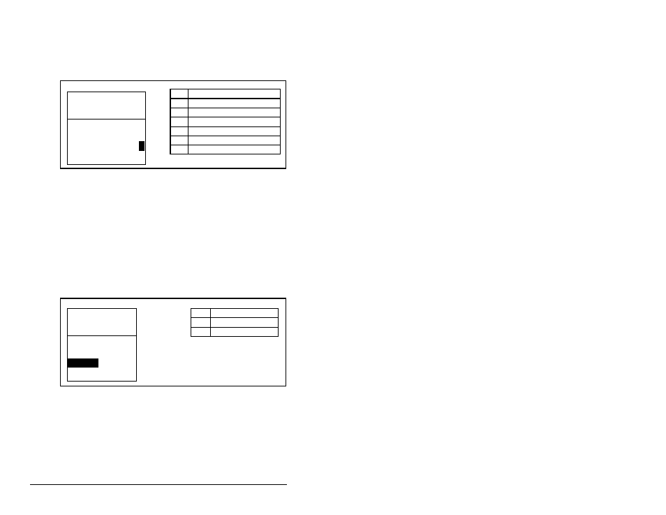
Step 3. Set the bits in M-S Output (26). This parameter determines
the data transmitted from the drive to the scanner. A “1”
enables the I/O. A “0” disables the I/O. Bit 0 is the
right-most bit. In figure 4.10, it is highlighted and equals
“1.”
Step 4. Reset the adapter. Refer to section 4.10 for this procedure.
The adapter is ready to receive I/O from the master (i.e., scanner).
You must now configure the scanner to recognize and transmit I/O
to the adapter. Refer to chapter 5, Configuring the Scanner.
4.7.2 Setting an Adapter To Transmit Peer-to-Peer
Data
Step 1. Verify that Peer Out Enable (41) is set to Off. This
parameter must be set to Off while you configure some of
the peer output parameters. See figure 4.11.
Step 2. Select the source of the data to output to the network in
Peer A Output A (39). If you are transmitting a 32-bit
Reference or 32-bit Datalink, only Peer A Output will be
available. Peer B Output cannot be used. See figure 4.12.
Figure 4.10 – Master-Slave Output Screen on an LCD OIM
Bit
Description
0
Status/Feedback (Default)
1
Datalink A Output
2
Datalink B Output
3
Datalink C Output
4
Datalink D Output
5-15
Not Used
Port 5 Device
RECOMM-DNET
Parameter #: 26
M-S Output
x x x x x x x x x x x 0 0 0 0
1
Status/Fdbk
b00
Figure 4.11 – Peer Out Enable Screen on an LCD OIM
Value
Setting
0
Off (Default)
1
On
Port 5 Device
RECOMM-DNET
Parameter #: 41
Peer Out Enable
0
Off