Rockwell Automation 1440-TPS02-01RB XM-320 Position Module User Manual
Page 60
Publication GMSI10-UM005C-EN-P - May 2010
52 Configuration Parameters
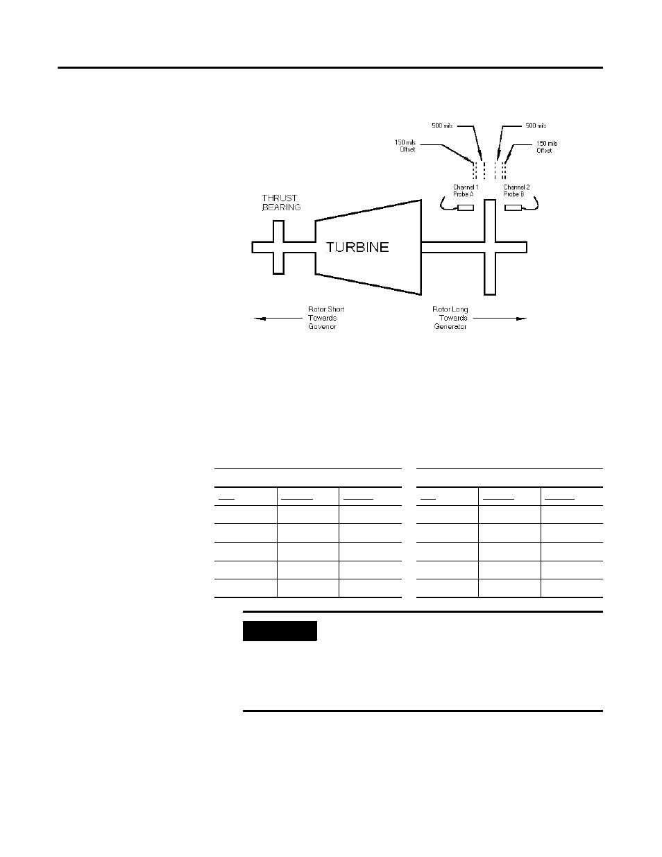
Figure 3.3 Head-to-Head Mode
The chart below shows gap-to-instrument reading-to-voltage outputs for
typical 500 mil transducers with an offset of 150 mils. Note that the offset gap
of a transducer is the gap closest to the transducer where the transducer’s
response to gap change becomes non-linear and not useful for measurement.
Install and gap the probes for their cold gap settings using the information
provided from previous installations or data provided in the Turbine manual.
This example assumes that the correct cold set point (Green line) is 250 mils,
the rotor is placed against the active thrust shoes, and the measurement range
is 0 to 1000 mils.
Note: The direction of differential growth for an upscale reading is away from Probe A and towards
Probe B.
Probe A
Probe B
Gap
Reading
Voltage
Gap
Reading
Voltage
150
0
-2.8
150
0
-3
250
100
-5.8
250
100
-6
400
250
-10.3
400
250
-10.5
550
400
-14.8
550
400
-15
650
500
-17.8
650
500
-18
IMPORTANT
Make certain the shaft is in its correct cold position or
compensate for the actual shaft axial position if it is known.
You can put the shaft into position by mechanically moving
it up against the active thrust shoe, or use the actual thrust
position to offset the transducer gap settings so that they
will be correct when the rotor is in the cold position.