Dlr network topology – Rockwell Automation 1769-L24ER-QB1B_L24ER-QBFC1B_L27ERM-QBFC1B CompactLogix 5370 L2 Controllers Quick Start User Manual
Page 80
80
Rockwell Automation Publication IASIMP-QS025B-EN-P - December 2012
Appendix A Understanding Other Application Options
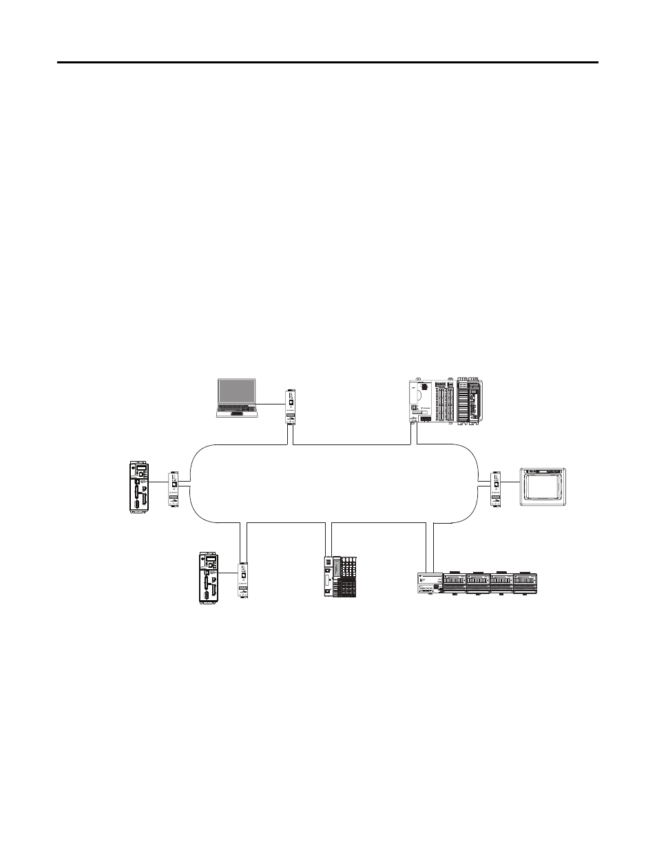
DLR Network Topology
A DLR network topology is a single-fault-tolerant ring network in which DLR-capable
Allen-Bradley devices use embedded technology and dual EtherNet/IP ports to establish a
network that is resilient to single points of failure, recovers faster when single faults occur, and
does not require switches.
Configuring a DLR network topology requires you to complete a few tasks that do not apply to
using a CompactLogix 5370 L2 controller in a linear or star network topology. For example, a
DLR network topology requires that one supervisor-capable network device be configured as
the active ring supervisor. CompactLogix 5370 L2 controllers are supervisor-capable devices on a
DLR network.
This graphic shows a DLR network topology with a CompactLogix 5370 L2 controller.
0 2
0
1734-AENTR
Module
Status
Network
Activity
Network
Status
Point Bus
Status
System
Power
Field
Power
POINT I O
Link 1
Activity/
Status
Link 2
Activity/
Status
IP ADDRESS
0
1
2
3
4
5
6
7
8
9
10
11
12 13
14
15
0
1
2
3
4
5
6
7
8
9
10
A0
B0
Z0
A1
B1
Z1
0
2 FUSE
1
3
OK
11
12 13
14
15
HIGH SPEED
C
O
UNTER
IN
OUT
DC
INPUT
24VDC
SINK\
SOURCE
24VDC
SOURCE
OUTPUT
DC
+24VDC COM
FG
0
1
2
3
4
5
6
7
8
9
10
11
12 13
14
15
0
1
2
3
4
5
6
7
8
9
10
A0
B0
Z0
A1
B1
Z1
0
2 FUSE
1
3
OK
11
12 13
14
15
HIGH SPEED
C
OUNTER
IN
OUT
DC
INPUT
24VDC
SINK\
SOURCE
24VDC
SOURCE
OUTPUT
DC
+24VDC COM
FG
00
01
02
03
04
05
06
07
NC
+V
00
01
02
03
04
05
06
07
COM
0
COM
0
08
09
10
11
12
13
14
15
NC
+V
08
09
10
11
12
13
14
15
COM
1
COM
1
A0+
B0+
Z0+
A1+
B1+
Z1+
+V
OUT
1
OUT
0
COM COM
A0-
B0-
Z0-
A1-
B1-
Z1-
+V
0UT
3
V
in
0+
V
in
2+
V
OUT
0+
I
OUT
0+
V
OUT
1+
I
in
3+
V
in
1+
I
in
1+
I
in
1+
V
in
3+
CJC
-
CJC
+
V/I
in
1-
V/I
in
3-
V/I
in
0-
V/I
in
2-
I
in
0+
I
in
2+
OUT
2
COM
COM
DC IN
HSC
DC OUT
ANALOG
00:00:BC:2E:69:F6
L27ERM
QBFC1B
CompactLogix 5370
L2 Control System
1794-AENTR FLEX™ I/O Adapter with
FLEX I/O Modules
PanelView Plus Terminal
Connected via a1783-ETAP
EtherNet/IP Tap
Computer Connected via a
1783-ETAP EtherNet/IP Tap
1734-AENTR POINT I/O
EtherNet/IP Adapter with
POINT I/O Modules
Kinetix 350 Drive
Connected via a1783-ETAP
EtherNet/IP Tap
Kinetix 350 Drive
Connected via a1783-ETAP
EtherNet/IP Tap