Install the system, Dc in hsc dc out analog – Rockwell Automation 1769-L24ER-QB1B_L24ER-QBFC1B_L27ERM-QBFC1B CompactLogix 5370 L2 Controllers Quick Start User Manual
Page 22
22
Rockwell Automation Publication IASIMP-QS025B-EN-P - December 2012
Chapter 1
Prepare the CompactLogix 5370 L2 Controller Hardware
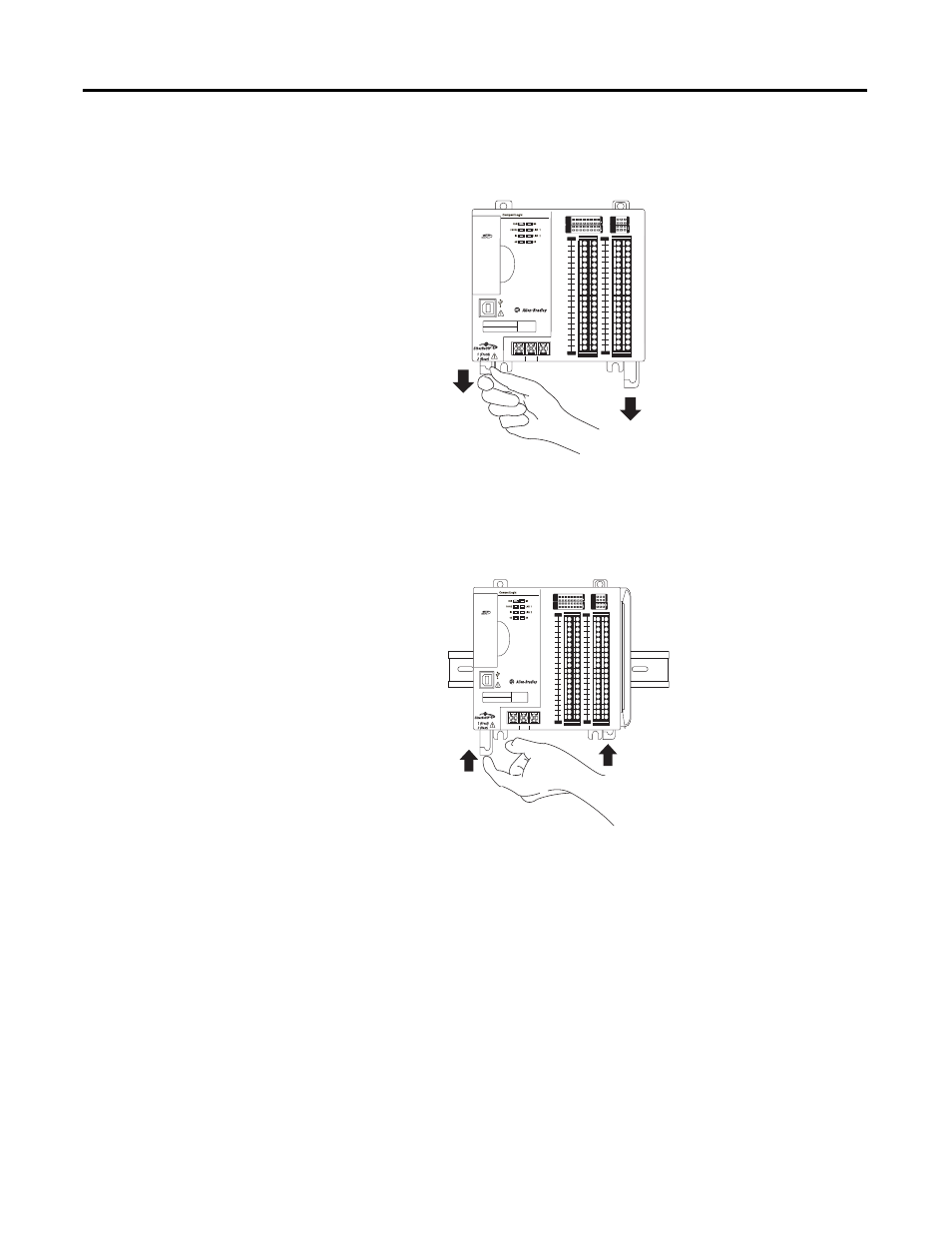
Install the System
1. Pull the bottom locking tabs out.
2. Hook the top of the controller on
the DIN rail.
3. Swing it downward until the
controller is flush against the DIN
rail and push it down against the
DIN rail.
4. Push the controller against the
DIN rail until the bottom DIN rail locks on the back of the controller click, locking the
controller in place.
5. Push the locking tabs in.
0
1
2
3
4
5
6
7
8
9
10
11
12 13
14
15
0
1
2
3
4
5
6
7
8
9
10
A0
B0
Z0
A1
B1
Z1
0
2 FUSE
1
3
OK
11
12 13
14
15
HIGH SPEED
C
OUNTER
IN
OUT
DC
INPUT
24VDC
SINK\
SOURCE
24VDC
SOURCE
OUTPUT
DC
+24VDC COM
FG
00
01
02
03
04
05
06
07
NC
+V
00
01
02
03
04
05
06
07
COM
0
COM
0
08
09
10
11
12
13
14
15
NC
+V
08
09
10
11
12
13
14
15
COM
1
COM
1
A0+
B0+
Z0+
A1+
B1+
Z1+
+V
OUT
1
OUT
0
COM COM
A0-
B0-
Z0-
A1-
B1-
Z1-
+V
0UT
3
V
in
0+
V
in
2+
V
OUT
0+
I
OUT
0+
V
OUT
1+
I
in
3+
V
in
1+
I
in
1+
I
in
1+
V
in
3+
CJC
-
CJC
+
V/I
in
1-
V/I
in
3-
V/I
in
0-
V/I
in
2-
I
in
0+
I
in
2+
OUT
2
COM
COM
DC IN
HSC
DC OUT
ANALOG
00:00:BC:2E:69:F6
L27ERM
QBFC1B
32256-M
0
1
2
3
4
5
6
7
8
9
10
11 12 13 14
15
0
1
2
3
4
5
6
7
8
9
10
A0 B0
Z0
A1 B1
Z1
0
2 FUSE
1
3
OK
11 12 13 14
15
HIGH SPEED
C
OUNTER
IN
OUT
DC
INPUT
24VDC
SINK\
SOURCE
24VDC
SOURCE
OUTPUT
DC
+24VDC COM
FG
00
01
02
03
04
05
06
07
NC
+V
00
01
02
03
04
05
06
07
COM
0
COM
0
08
09
10
11
12
13
14
15
NC
+V
08
09
10
11
12
13
14
15
COM
1
COM
1
A0+
B0+
Z0+
A1+
B1+
Z1+
+V
OUT
1
OUT
0
COM COM
A0-
B0-
Z0-
A1-
B1-
Z1-
+V
0UT
3
V
in
0+
V
in
2+
V
OUT
0+
I
OUT
0+
V
OUT
1+
I
in
3+
V
in
1+
I
in
1+
I
in
1+
V
in
3+
CJC
-
CJC
+
V/I
in
1-
V/I
in
3-
V/I
in
0-
V/I
in
2-
I
in
0+
I
in
2+
OUT
2
COM
COM
DC IN
HSC
DC OUT
ANALOG
00:00:BC:2E:69:F6
L27ERM
QBFC1B
32257-M