Make an ethernet/ip network connection, Set network ip address, Important – Rockwell Automation 1769-L24ER-QB1B_L24ER-QBFC1B_L27ERM-QBFC1B CompactLogix 5370 L2 Controllers Quick Start User Manual
Page 28: Dc in hsc dc out analog
28
Rockwell Automation Publication IASIMP-QS025B-EN-P - December 2012
Chapter 1
Prepare the CompactLogix 5370 L2 Controller Hardware
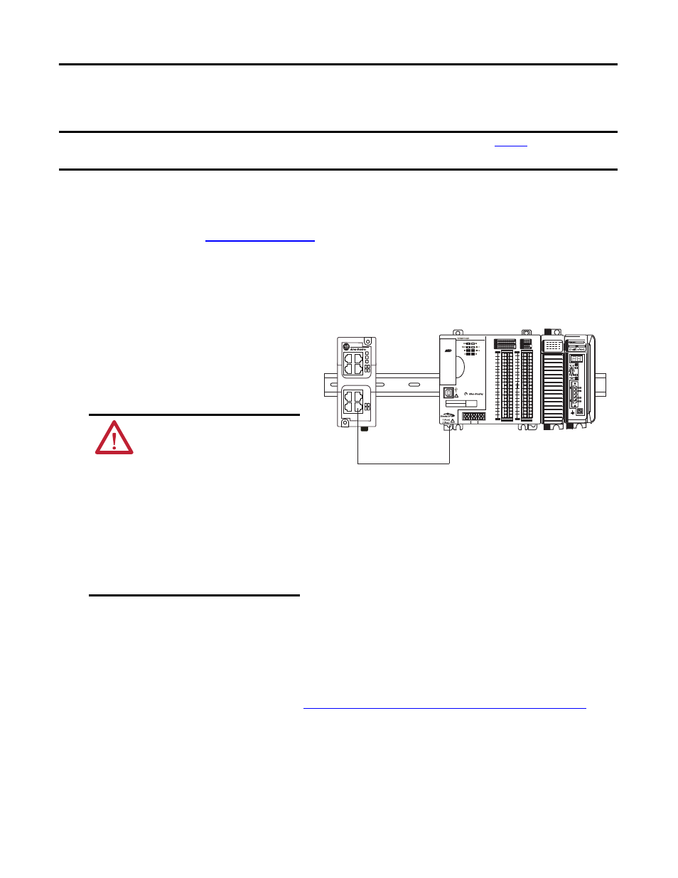
Make an EtherNet/IP Network Connection
This quick start describes a basic EtherNet/IP network connection. You can use
CompactLogix 5370 L2 controllers in multiple EtherNet/IP network topologies as described in
the publications listed in
.
1. Plug a 1585J-M4TBJM-1, Ethernet cable (straight-through) into a port on the
Stratix 6000 switch.
2. Plug the other end of the Ethernet
cable into one of the Ethernet
ports on the bottom of the
controller.
Set Network IP Address
Once you connect the CompactLogix 5370 L2 controller to an EtherNet/IP network, you must
assign the controller a unique IP address. For information about how to set the network IP
address for your controller, see Chapter 3,
Configure the EtherNet/IP Network on page 47
.
IMPORTANT
ATTENTION: This section assumes you installed an EtherNet/IP network as described on
and the network
includes a 1783-EMS08T switch.
WARNING: If you connect or
disconnect the communication
cable with power applied to this
module or any device on the
network, an electrical arc can
occur. This could cause an
explosion in hazardous location
installations.
Be sure that power is removed or the
area is nonhazardous before
proceeding.
0
1
2
3
4
5
6
7
8
9
10
11
12 13
14
15
0
1
2
3
4
5
6
7
8
9
10
A0
B0
Z0
A1
B1
Z1
0
2 FUSE
1
3
OK
11
12 13
14
15
HIGH SPEED
C
OUNTER
IN
OUT
DC
INPUT
24VDC
SINK\
SOURCE
24VDC
SOURCE
OUTPUT
DC
+24VDC COM
FG
00
01
02
03
04
05
06
07
NC
+V
00
01
02
03
04
05
06
07
COM
0
COM
0
08
09
10
11
12
13
14
15
NC
+V
08
09
10
11
12
13
14
15
COM
1
COM
1
A0+
B0+
Z0+
A1+
B1+
Z1+
+V
OUT
1
OUT
0
COM COM
A0-
B0-
Z0-
A1-
B1-
Z1-
+V
0UT
3
V
in
0+
V
in
2+
V
OUT
0+
I
OUT
0+
V
OUT
1+
I
in
3+
V
in
1+
I
in
1+
I
in
1+
V
in
3+
CJC
-
CJC
+
V/I
in
1-
V/I
in
3-
V/I
in
0-
V/I
in
2-
I
in
0+
I
in
2+
OUT
2
COM
COM
DC IN
HSC
DC OUT
ANALOG
00:00:BC:2E:69:F6
L27ERM
QBFC1B
1
2
3
4
5
6
7
8