Plc-3, Family processors ladder logic – Rockwell Automation 1771-DB BASIC MODULE User Manual
Page 83
Chapter
Programming Block-Transfers
5
5 -9
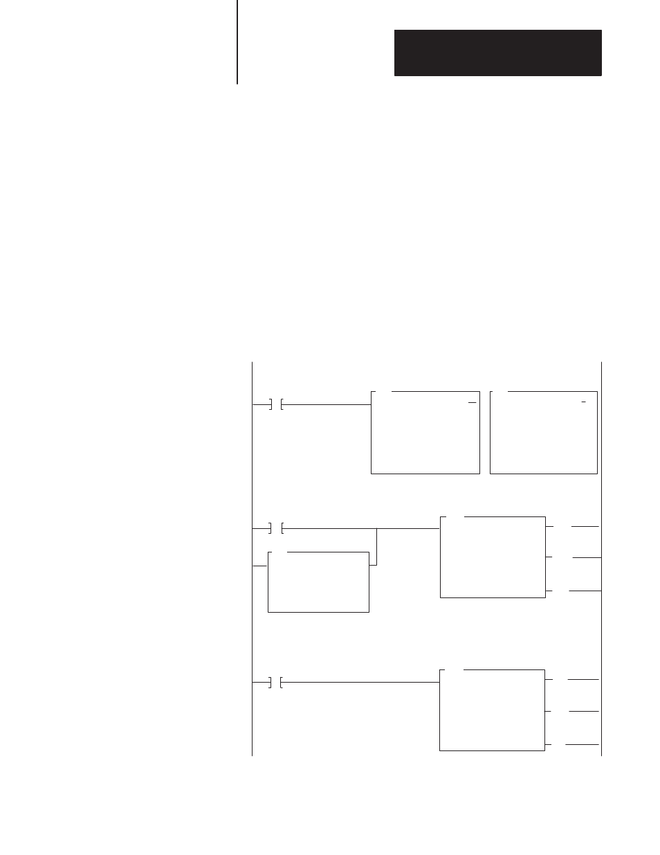
You can use this ladder logic program with PLC-3 or PLC-3/10 processors.
This program assumes that your application requires a single BTR and
BTW to pass data between the processor and the BASIC module (transfer
of 64 words or less). If the transferred data exceeds 64 words you must
program multiple file to file moves to move different data sets to and from
the block-transfer files.
Rung one is true only at power-up. It uses status word 3, bit 3 (the ac
power loss bit of the PLC-3) to zero the control file of both the BTR and
BTW. In Rungs 2 and 3, during normal program execution the BTW and
BTR instructions are alternately executed. The done bits of each
instruction enable the next block-transfer instruction. The BTR and BTW
control files must be different for the next block-transfer to occur.
The equal instruction is used at power-up. At power-up the BTR and BTW
control files both equal zero. At power-up the BTW enables and
block-transfers begin.
XOR
A XOR B = R
A : WB001:0030
0000000010000100
B : WB001:0030
0000000010000100
R : WB001:0030
0000000010000100
BTW
BLOCK XFER WRITE
RACK :
GROUP :
MODULE:
002
1
1 = HIGH
FB002:0150
5
FB001:0030
DATA:
LENGTH =
CNTL
XOR
A XOR B = R
A : WB001:0020
0000000000000000
B : WB001:0020
0000000000000000
R : WB001:0020
0000000000000000
S0003
03
WB001:0020
15
EQU
A = B
A : WB001:0030
0000000010000100
B : WB001:0020
0000000000000000
CNTL
02
CNTL
05
CNTL
03
WB001:0030
05
BTR
BLOCK XFER READ
RACK :
GROUP :
MODULE:
002
1
1 = HIGH
FB002:0220
5
FB001:0020
DATA:
LENGTH =
CNTL
CNTL
12
CNTL
15
CNTL
13
RUNG NUMBER RM1
RUNG NUMBER RM2
RUNG NUMBER RM3
1
2
3
(LE)
(DN)
(ER)
(LE)
(DN)
(ER)
PLC-3
Family Processors
Ladder Logic