Communication modes, Prt1 and prt2 port – Rockwell Automation 1771-DB BASIC MODULE User Manual
Page 40
Chapter
Using the Communication Ports
2
2 -2
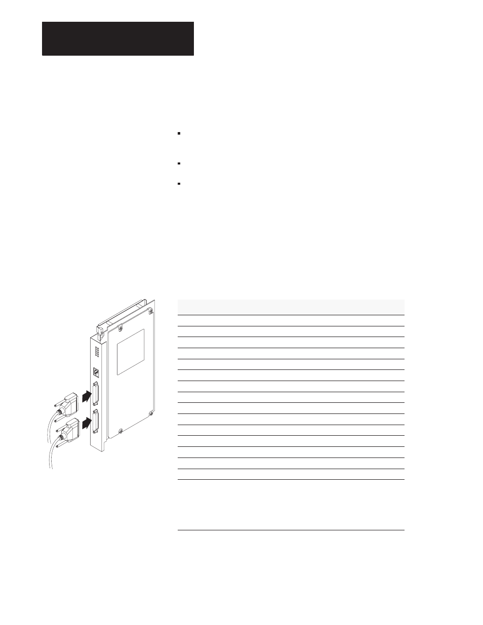
PRT1 and PRT2 Port
You can configure ports PRT1 and PRT2 for these communication modes:
RS-232C – communicate with a RS-232 device or an unterminated
RS-423 device within 50 ft.
RS-422 – point to point and multidrop for RXD/TXD connections
RS-485 – multidrop supported for RXD/TXD connections
The communication mode you choose depends on the device you are
connecting to the BASIC module. Refer to the documentation
accompanying the device. JW8 sets the communication mode for port
PRT1 (page 1 -9) and JW9 sets (page 1 -9) the communication mode for
port PRT2 .
PRT1 and PRT2 Pinout Connections
PRT1 and PRT2 have a DB25 female connector. Here is the pinout for the
connectors:
Pin
RS-232
RS-422
RS-485
1
chassis/shield
chassis/shield
chassis/shield
2
TXD
N/A
②
N/A
②
3
RXD
N/A
②
N/A
②
4
RTS
N/A
②
N/A
②
5
CTS
N/A
②
N/A
②
6
DSR
N/A
②
N/A
②
7
common
common
common
8
DCD
N/A
②
N/A
②
9
common
common
common
10
common
common
common
14
N/A
①
TXD
TXD/RXD
16
N/A
①
RXD
N/A
②
18
N/A
①
RXD’
N/A
②
20
DTR
N/A
②
N/A
②
25
N/A
①
TXD’
TXD’/RXD’
①
These pins are not a No Connection (N/C). In RS-232 mode, the RS-422 and RS-485
load is still present and should not be connected to any device in this mode.
②
In RS-422 and RS-485 modes, these pins are still connected to their RS-232 drivers
and receivers. Do not use these pins in either RS-422 or RS-485 mode.
Important: Pins 11, 12, 13, 15, 17, 19, 21, 22, 23 and 24 are a No Connection (N/C)
PRT1 and PRT2 are electrically isolated to 500V dc.
Communication Modes
20376–M