Input and output arguments – Rockwell Automation 1771-DB BASIC MODULE User Manual
Page 215
Chapter
Call Routines 0–68
12
12 -25
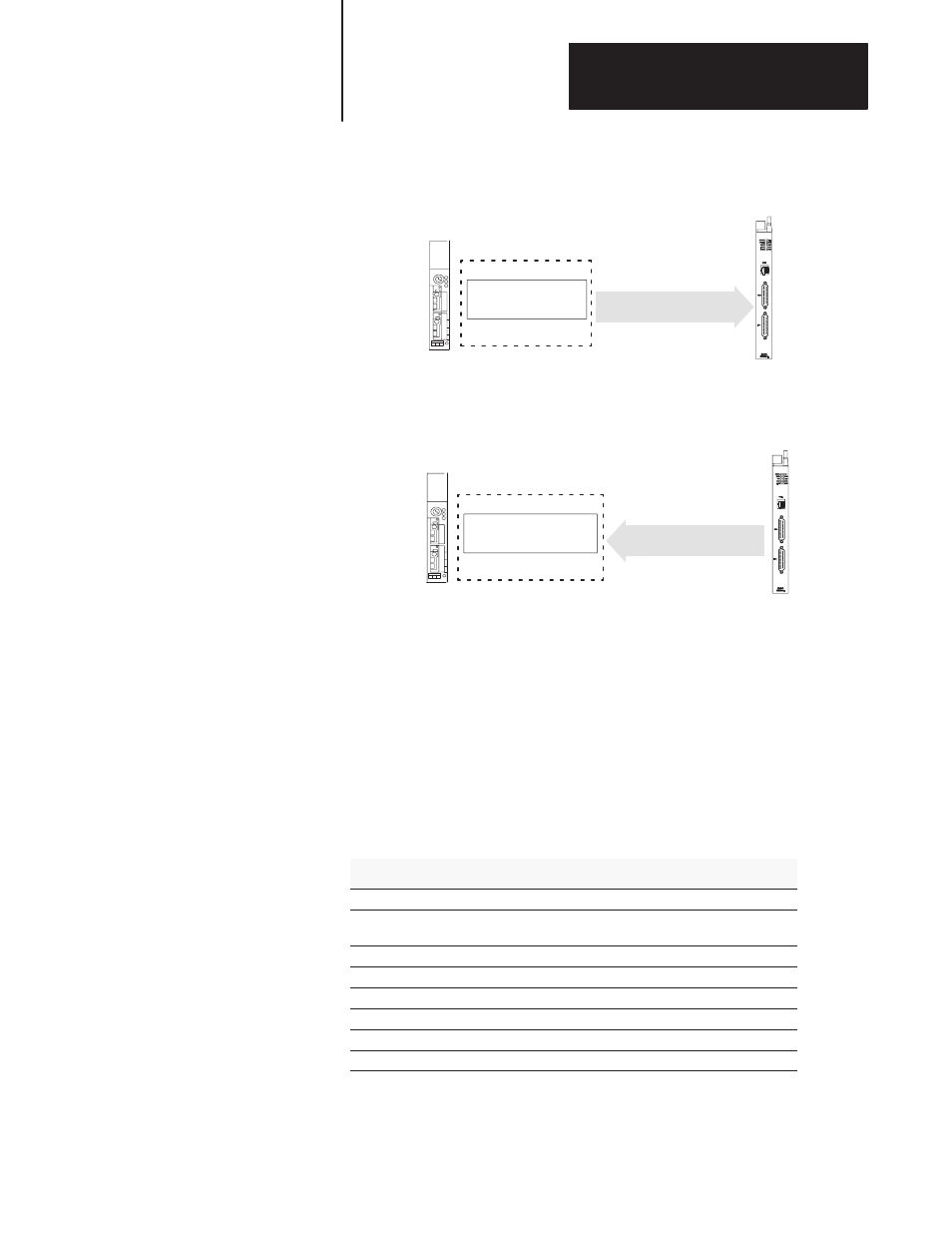
4.
The ladder logic program of the PLC processor retrieves the data
from the input image table and performs a block transfer
PLC Processor
Block Transfer
BASIC Module
PLC Backplane
PRT2
PRT1
5.
The BASIC module resets the bit in the PLC input image table on the
same end of the scan cycle in which the block transfer is performed.
Reset Input Image Table
Bit 10 or 12
PLC Processor
BASIC Module
PLC Backplane
PRT2
PRT1
Data transfers continue until you re-execute the call for the port with
different input parameters. If this occurs, the previous CALL 33 for the
port is automatically disabled and the new CALL 33 takes effect.
You cannot execute multiple CALL 33s for the same port in parallel.
However, you can activate PRT1 and PRT2 simultaneously by issuing
separate CALL 33s.
Input and Output Arguments
This routine has seven input arguments and one output argument.
Argument
Description
Page
input 1
source port of BASIC module
12 -26
input 2
maximum number of 8-bit characters you want to copy
from the BASIC serial port to the destination file
12 -26
input 3
decimal value of the ASCII character delimiter
12 -26
input 4
selection of the destination buffer
12 -26
input 5
always 1
12 -27
input 6
the string number
12 -27
input 7
byte swap selection
12 -27
output 1
call status
12 -27