Rockwell Automation 1771-DB BASIC MODULE User Manual
Page 221
Chapter
Call Routines 0–68
12
12 -31
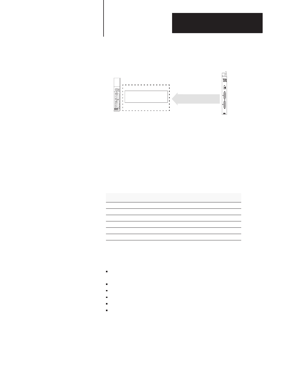
6.
The BASIC module resets the input image table bit 11 or bit 13 on
the same end of scan cycle in which the output image table bit 11 or
bit 13 was reset.
Reset Input Image Table
Bit 11 or 13
PLC Processor
BASIC Module
PLC Backplane
Transfers continue in this manner until you re-execute the call for the port
with different input parameters. If this occurs, the previous CALL 34 for
the port is automatically disabled and the new CALL 34 takes effect.
You cannot execute multiple CALL 34s for the same port in parallel.
However, you can activate port PRT1 and port PRT2 simultaneously by
issuing separate CALL 34s for these ports.
Input and Output Arguments
This CALL has five input arguments and one output argument.
Argument
Description
Page
input 1
destination of the data
12 -31
input 2
always 0
12 -32
input 3
always 1
12 -32
input 4
internal string number
12 -32
input 5
byte swap selection
12 -32
output 1
call status
12 -32
Input Argument One
The first input argument is the destination of the data. You can choose the
port number (1 or 2) and/or the internal string:
0 = disable CALL 34 for all active ports and strings enabled by earlier
CALL 34s
1 = internal string only
2 = port PRT1
3 = internal string and port PRT1
4 = port PRT2
5 = internal string and port PRT2
If you choose an internal string (1, 3, or 5), the first character of the string
contains the byte count. The second character (transaction number)
increments to inform the BASIC module that new data is in the string.
The value of this character wraps around from 255 to 0. The data from the
source buffer begins with the third character of the string.