C - troubleshooting, What’s in this appendix, Interpret the indicator lights – Rockwell Automation 1771-DB BASIC MODULE User Manual
Page 349: Troubleshooting
C
Appendix
C –1
Troubleshooting
This appendix describes:
On page:
interpret the indicator lights
error messages from BASIC
error messages from CALL routines
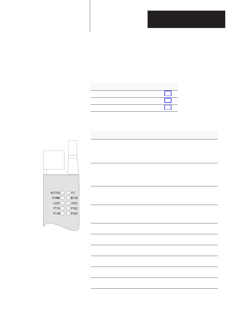
The BASIC module has 10 indicator LED indicators.
If this LED:
Status is:
This indicates:
ON
the BASIC module is receiving power from the backplane
and is executing BASIC code
ACTIVE (green) blinking
the BASIC module is in Command mode
OFF
the BASIC module is not receiving power from the
backplane. A fault condition exists.
FLT (red)
ON
a system problem was detected during background
diagnostics. Contact your local Allen–Bradley
representative.
FLT (red)
OFF
no system problems detected during background
diagnostics
ON
port DH485 on the BASIC module is active for
communication
DH485 (green)
OFF
port DH485 on the BASIC module is not active for
communication
ON
the voltage of the battery that backs up RAM is low. A new
battery is needed. See Chapter 3.
BTLO (red)
OFF
the voltage of the battery that backs up RAM is at an
acceptable level
ON
user definable. LED activated through the user program.
LED1 (amber)
OFF
user definable. LED de-activated through the user program.
ON
user definable. LED activated through the user program.
LED2 (amber)
OFF
user definable. LED de-activated through the user program.
blinking
port PRT1 on the BASIC module is transmitting signals
PT1X (green)
OFF
port PRT1 on the BASIC module is not transmitting signals
blinking
port PRT2 on the BASIC module is transmitting signals
PT2X (green)
OFF
port PRT2 on the BASIC module is not transmitting signals
blinking
port PRT1 on the BASIC module is receiving signals
PT1R (green)
OFF
port PRT1 on the BASIC module is not receiving signals
blinking
port PRT2 on the BASIC module is receiving signals
PT2R (green)
OFF
port PRT2 on the BASIC module is not receiving signals
What’s in This Appendix?
Interpret the Indicator Lights