Output data file, Output module’s input data file – Rockwell Automation 1769-ADN Compact I/O 1769-ADN DeviceNet Adapter User Manual
Page 39
Publication 1769-UM001B-EN-P - October 2002
How Communication Takes Place and I/O Image Table Mapping 2-15
1769-OW16 AC/DC Relay
Output Module (16 Point)
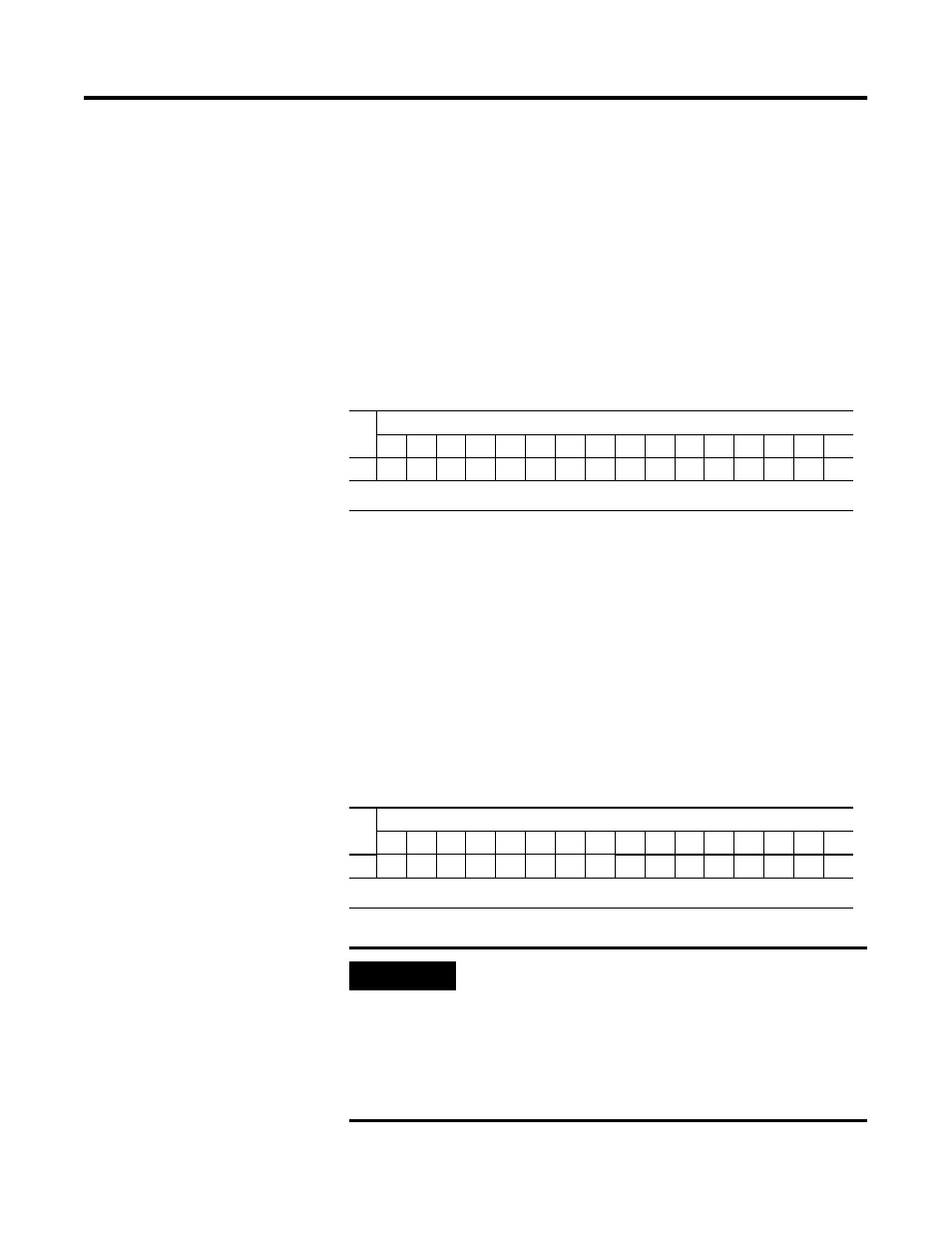
Output Data File
Data output bits are turned on or off using the bit positions in Word 0.
1 = output on
0 = output off
Example: To turn on bit position 12, type 1 in Word 0, Bit 12.
For each module, slot x, word 0 in the output data file contains the
control program’s directed state of the discrete output points.
Output Module’s Input Data File
For each module, slot x, input data file word 0 contains the state of
the module’s output data (output data echo) file word 0. During
normal operation, these input bits represent the logic state that the
outputs are directed to by the control program. They are also
dependent upon the:
• Program Mode configuration (if supported by the controller)
• The Fault Mode configuration (if supported by the controller).
Wo
rd
Bit Position
15
14
13
12
11
10
9
8
7
6
5
4
3
2
1
0
0
w
w
w
w
w
w
w
w
w
w
w
w
w
w
w
w
w = write only
Wo
rd
Bit Position
15
14
13
12
11
10
9
8
7
6
5
4
3
2
1
0
0
r
r
r
r
r
r
r
r
r
r
r
r
r
r
r
r
r = read only
IMPORTANT
The output module’s input data file reflects the
output data echo of the module, not necessarily the
electrical state of the output terminals. It does not
reflect shorted or open outputs.
It is important to use this input word if the controller
adapter supports the Program Mode or Fault Mode
function, and if it is configured to use them.