Adapter status words – Rockwell Automation 1769-ADN Compact I/O 1769-ADN DeviceNet Adapter User Manual
Page 26
Publication 1769-UM001B-EN-P - October 2002
2-2 How Communication Takes Place and I/O Image Table Mapping
The amount of input data in the adapter’s input image for each I/O
module is based on the configuration of each I/O module done as
part of the 1769-ADN configuration. If an I/O module is configured to
have 0 words of input data, then it does not appear in the input image
of the 1769-ADN.
Adapter Status Words
The first two words (0 and 1) of the adapter input image contain the
adapter status. The adapter status consists of:
• I/O module data invalid bits - 1 status bit for each slot
• node address changed - 1 bit
...
...
...
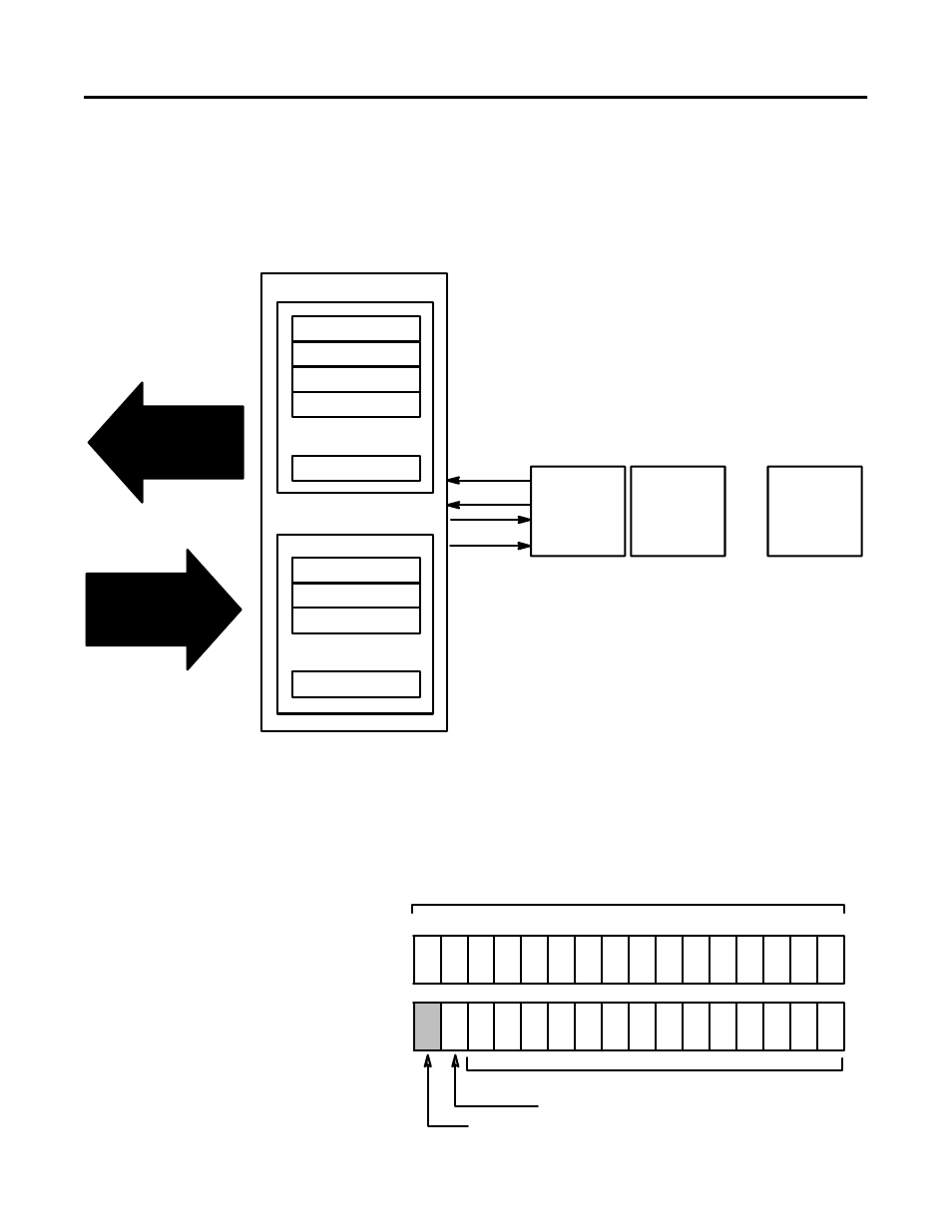
Network READ
Network WRITE
DeviceNet Adapter
Input Image (Read Data)
Output Image (Write Data)
Read
Write
I/O Module
Slot 1
I/O Module
Slot 2
I/O Module
Slot 30
42279
Slot 30 Output Data
Slot 3 Output Data
Slot 2 Output Data
Slot 30 Input Data
Slot 3 Input Data
Slot 2 Input Data
Slot 1 Input Data
Adapter Status Words
Slot 1 Output Data
Bit:
9
8
7
6
5
4
3
2
1
0
I/O Module Data Invalid Bits
Node Address Changed Bit (NACB)
Sl
ot
7
Sl
ot
6
Sl
ot
5
Sl
ot
4
Sl
ot
3
Sl
ot
2
Sl
ot
1
42280
10
11
12
13
14
15
Sl
ot
8
Sl
ot
9
Sl
ot
10
Sl
ot
11
Sl
ot
12
Sl
ot
13
Sl
ot
14
Sl
ot
15
24
23
22
21
20
19
18
17
16
25
26
27
28
29
30
Sl
ot
26
Sl
ot
27
Sl
ot
28
Sl
ot
29
Sl
ot
30
NA
CB
Sl
ot
19
Sl
ot
20
Sl
ot
21
Sl
ot
22
S
lot
23
Sl
ot
24
Sl
ot
25
Sl
ot
18
Sl
ot
17
Word 0
Word 1
I/O Module Data Invalid Bits
Spare, not used
Sl
ot
16