Output data, Input data – Rockwell Automation 1769-ADN Compact I/O 1769-ADN DeviceNet Adapter User Manual
Page 35
Publication 1769-UM001B-EN-P - October 2002
How Communication Takes Place and I/O Image Table Mapping 2-11
1769-OF2 (Series A and B)
Analog Current/Voltage
Output Module (2 Channel)
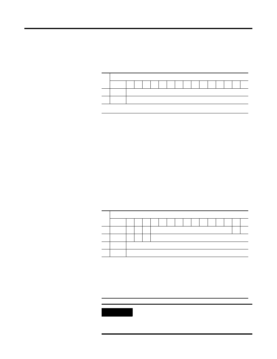
Output Data
For each 1769-OF2 module, output data words 0 and 1 contain the
channel 0 and channel 1 output data.
Input Data
For each 1769-OF2 module, input data words 0-1 contain analog
status and error information. Input data words 2-3 contain the state of
the module’s output data (output data echo) words 0-1. During
normal operation (controller in Run), these input words represent the
analog values that the outputs are directed to by the control program.
They are also dependent upon the:
• Program Mode configuration (Hold Last or User-Defined Safe
State)
• Fault Mode configuration (Hold Last or User-Defined Safe State)
Wo
rd
Bit Position
15
14 13 12 11 10
9
8
7
6
5
4
3
2
1
0
0
SGN
Analog Output Data Channel 0
1
SGN
Analog Output Data Channel 1
SGN= sign bit in two’s compliment format
Wo
rd
Bit Position
15
14 13 12 11 10
9
8
7
6
5
4
3
2
1
0
0
D0
H0 D1 H1
Not Used (Bits set to 0)
S1 S0
1
U0
O0 U1 O1
Bits set to 0
2
SGN
Output Data Loopback/Echo Channel 0
3
SGN
Output Data Loopback/Echo Channel 1
SGN= sign bit in two’s format
Sx = general status bits. When set, these bits indicate an error (over-range, under-range, or
diagnostic bit) associated with that channel or a module hardware error.
Ux = under-range flag bits
Ox = over-range flag bits
Dx = diagnostic bits. When set, they indicate a broken output wire or high load resistance
(not used on voltage outputs).
Hx = hold last state bits. When set, they indicate that the channel is in a hold last state condition.
IMPORTANT
The output module’s input data reflects the analog
output data echo of the module, not necessarily the
electrical state of the output terminals. It does not
reflect shorted or open outputs.