Input data – Rockwell Automation 1769-ADN Compact I/O 1769-ADN DeviceNet Adapter User Manual
Page 30
Publication 1769-UM001B-EN-P - October 2002
2-6 How Communication Takes Place and I/O Image Table Mapping
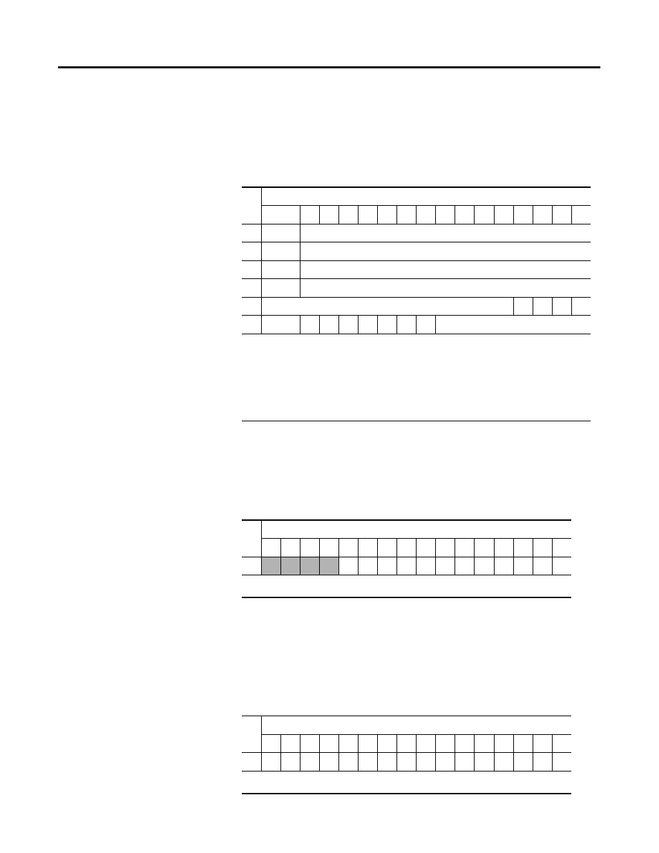
1769-IF4 (Series A and B)
Analog Current/Voltage
Input Module (4 Channel)
Input Data
For each 1769-IF4 input module, input data words 0-3 contain the
analog value of the inputs. Word 4 and 5 contain analog status and
error information.
1769-IM12 240V AC Input
Module (12 Point)
Input Data
For each 1769-IM12 input module, input data word 0 contains the
current state of the field input points. Bits 12 to 15 are not used.
1769-IQ16 24V DC
Sink/Source Input Module
(16 Point)
Input Data
For each 1769-IQ16 input module, input data word 0 contains the
current state of the field input points.
Wo
rd
Bit Position
15
14 13 12 11 10
9
8
7
6
5
4
3
2
1
0
0
SGN
Analog Input Data Channel 0
1
SGN
Analog Input Data Channel 1
2
SGN
Analog Input Data Channel 2
3
SGN
Analog Input Data Channel 3
4
Not Used
S3 S2 S1 S0
5
U0
O0 U1 O1 U2 O2 U3 O3
Set to 0
SGN= sign bit in two’s format
Sx = general status bit for channels 0 through 3. This bit is set (1) when an error (over- or
under-range) exists for that channel.
Ux = under-range flag bits for channels 0 through 3. These bits can be used in the control
program for error detection.
Ox = over-range flag bits for channels 0 through 3. These bits can be used in the control
program for error detection.
Wo
rd
Bit Position
15 14 13 12 11 10
9
8
7
6
5
4
3
2
1
0
0
0
0
0
0
r
r
r
r
r
r
r
r
r
r
r
r
r = read
Wo
rd
Bit Position
15 14 13 12 11 10
9
8
7
6
5
4
3
2
1
0
0
r
r
r
r
r
r
r
r
r
r
r
r
r
r
r
r
r = read