Application examples, Chapter, 1747-sdn application example – Rockwell Automation 1769-ADN Compact I/O 1769-ADN DeviceNet Adapter User Manual
Page 113: Hardware setup configuring the slc system, You’ll need to enter your slc 500
1
Publication 1769-UM001B-EN-P - October 2002
Chapter
6
Application Examples
1747-SDN Application
Example
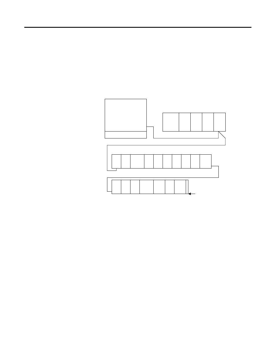
The following application example details a 1747-SDN DeviceNet
scanner controlling 1769 Compact I/O via DeviceNet and the
1769-ADN DeviceNet Adapter.
Hardware Setup
Configuring the SLC System
You’ll need to enter your SLC 500
TM
programming software, create a
new program, and choose the SLC 5/04 processor to configure the
SLC system.
This example uses a 1747-SDN DeviceNet scanner in slot 3. The
software automatically creates 32 I/O words and 256 M1 and M0 file
words. You can view this by highlighting the 1747-SDN in the I/O
configuration screen and choosing Advanced Config.
The 1747-SDN maps the 1769 I/O to the I/O image words in the SLC
processor. You can then write a ladder program addressing this I/O.
Since the I/O data is packed into the SLC I/O image, you’ll want to
see where this data is actually mapped before attempting to address it
in the ladder program. For additional details on configuring your SLC
system and writing the ladder program, refer to the SLC 500 and
MicroLogix
TM
1000 Instruction Set (publication 1747-RM001), the
MicroLogix 1200 and 1500 Instruction Set (publication 1762-RM001),
the SLC 500 Modular Hardware Style User Manual (publication
1747-RM011), and/or the RSLogix 500 help screens.
Notebook Computer
with RSLogix 500
TM
,
RSLinx
TM
, RSNetworx
for DeviceNet, and a
1784-PCD DeviceNet
interface card
1746-P2
SLC 5/04
1747-SDN
1769-
ADN
1769-
IA16
1769-PB2
1769-
OW8
1769-
IA16
1769-
OW8
1769-
IQ6X
OW4
1769-
IQ6X
OW4
1769-
IQ16
1769-
OV16
1769-
IF4
1769-
OF2
1769-
IQ16
1769-PA2
1769-
OB16
1769-
IQ16
1769-
OV16
1769-ECR
1769-CRL
DeviceNet Cable
42321