Interpreting the led indicators, Interpreting the led indicators -3 – Rockwell Automation 1746-NO8V SLC 500 8-Point Analog Output Module/ User Manual User Manual
Page 55
Publication 1746-UM026A-EN-P - September 2003
Module Diagnostics and Troubleshooting 6-3
Interpreting the LED
Indicators
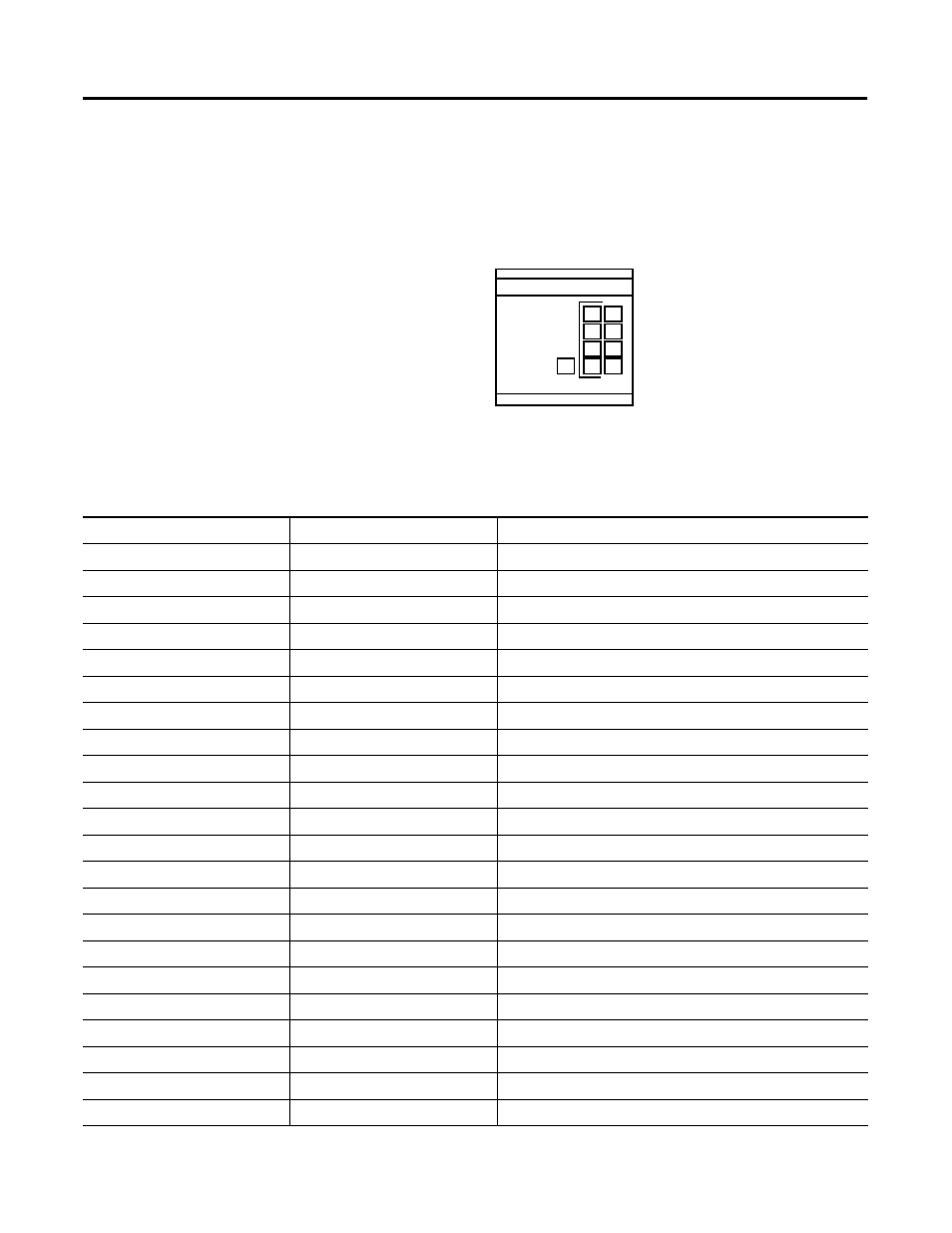
The module has 9 LEDs:
•
8 channel status LEDs (for Channels 0 through 7)
•
1 module status LED
Figure 6.1 Module LEDs
Use the following table to interpret the LEDs:
OUTPUT
CHANNEL
STATUS
MODULE
ANALOG
0
1
2
3
4
5
6
7
Table 6.1 1746-NO8 LED Indications
Module LED Status
Channel LED Status
Indicates
On solid
On solid
The channel is enabled.
On solid
On flashing, 1-flash sequence
Open circuit.
On solid
On flashing, 2-flash sequence
Unused configuration word bits are set
On solid
On flashing, 3-flash sequence
Illegal range
On solid
On flashing, 4-flash sequence
Illegal format
On solid
On flashing, 5-flash sequence
Illegal parameter ID
On solid
On flashing, 6-flash sequence
User range error (e.g. User_min > User_max)
On solid
On flashing, 7-flash sequence
Clamp range error
On solid
On flashing, 8-flash sequence
Illegal fault action
On solid
On flashing, 9-flash sequence
illegal ramp value
On solid
On flashing, 10-flash sequence
Illegal limit range
On solid
On flashing, 11-flash sequence
Illegal preset
On solid
On flashing, 12-flash sequence
Illegal optional features
On solid
Off
Module is powering up or the channel is disabled.
On flashing, 1-flash sequence
n/a
24V power fail or J4 jumper is missing
On flashing, 2-flash sequence
n/a
Configuration error
On flashing, 3-flash sequence
n/a
EEPROM fault
On flashing, 4-flash sequence
n/a
RAM fault
On flashing, 5-flash sequence
n/a
Input access error
On flashing, 6-flash sequence
n/a
Output access error
On flashing, 7-flash sequence
n/a
ROM CRC failed
Off
n/a
Module fault condition