5 - i/o data and status information, Output image and input image overview, Chapter 5 – Rockwell Automation 1746-NO8V SLC 500 8-Point Analog Output Module/ User Manual User Manual
Page 45: I/o data and status information, Output image and input image overview -1, Output image -1, Chapter
1
Publication 1746-UM026A-EN-P - September 2003
Chapter
5
I/O Data and Status Information
Read this chapter to:
•
monitor each output channel
•
check each channel’s configuration and status
Output Image and Input
Image Overview
Output Image
The output image (defined as the output from the SLC processor to
the module) defines how each channel on your module works.
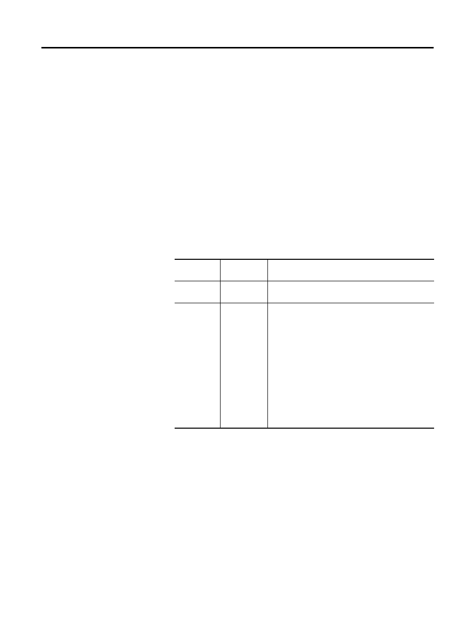
Table 5.1 1746-NO8 Output Image Operation
Operating
Mode
Output
Image Size
Module Operation
Class 1
8-word
The output data words control the output signal level for
each channel.
Class 3
32-word
•
The output data words control the output signal
level for each channel.
•
The configuration words replace configuration
DIP switches that may be used on other modules.
Each configuration word configures one channel.
•
The output data parameters 1 and 2 typically
define low and high values for items such as limit
alarms and output clamping. Ramping and preset
output on fault only use output data parameter 1.
•
Important - Class 3 features for any particular
channel will only be active if the channel is
enabled. Disabled channels will output 0V (0 mA)
no matter what features are configured.