Rockwell Automation 1746-NO8V SLC 500 8-Point Analog Output Module/ User Manual User Manual
Page 39
Publication 1746-UM026A-EN-P - September 2003
Configuring the Module 4-15
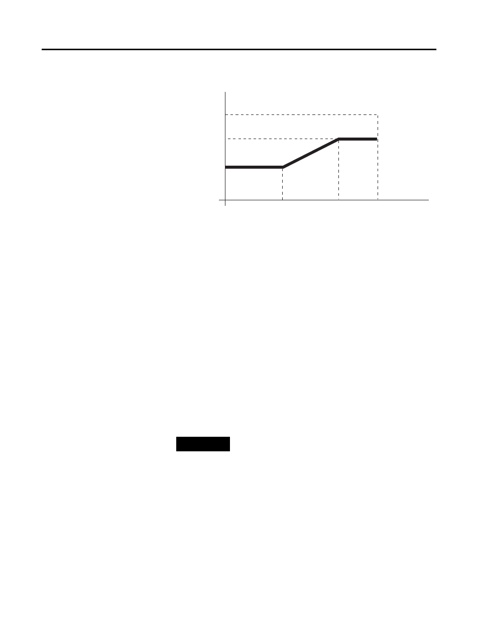
Figure 4.4 Output Clamping Example Data Output
Note that whenever the requested output data values meet or
attempt to exceed the output data limits, the module sets bits 9 or
10 in Input Status Word 2 (I:e.8 for Channel 0) to indicate a clamp
alarm.
Set Limit Alarm Values
This feature allows alarming if the output value from the module is
the same or higher than the limit alarm high value or the same or
lower than the limit alarm low value. It can be set on a
channel-by-channel basis. The limit alarm low and high values are
configured by placing the desired value into the Output Data
Parameter Word 1 and 2, respectively, for the desired channel then
setting the Output Configuration Word for the channel to Set the Limit
Alarm Values
The limit alarm values are based on the same data format and output
range configured for the channel.
EXAMPLE 3: Set Limit Alarm Values
Suppose you have a valve connected to Channel 6 with a 0 to 20
mA operating range and you want to use the 1746-NO4 compatible
format. You would use the following settings for the Channel 6
configuration word.
10V
-10,000
8V
2V
-10V
-210,000
+8,000
+10,000
TIP
For some ranges and formats, the limit alarms will
occur a few counts off from the set limit alarm
values. You may need to adjust the limit alarm values
until the desired alarm limit occurs.