Wiring procedure -10, Wiring procedure – Rockwell Automation 1746-NO8V SLC 500 8-Point Analog Output Module/ User Manual User Manual
Page 18
Publication 1746-UM026A-EN-P - September 2003
2-10 Installation and Wiring
Wiring Procedure
To wire your module, follow these steps:
1. Determine the length of cable you need to connect a channel to
its field device. Remember to include additional cable to route
the shield wire and foil shield to their ground points.
2. At each end of the cable, strip some casing to expose the
individual wires.
3. Trim the exposed signal wires to 50 mm (2 in) lengths. Strip
about 5 mm (3/16 in.) of insulation away to expose the end of
each wire.
4. At one end of the cable, twist the shield wire and foil shield
together, bend them away from the cable, and apply shrink
wrap.
5. At the other end of the cable, cut the drain wire and foil shield
back to the cable and apply shrink wrap.
6. Connect the wires to the terminal block and field device as
shown in Figure 2.1 on page 2-11. The recommended maximum
terminal screw torque is 0.7 to 0.9 Nm (6 to 8 in-lb) for all
terminal screws. Excessive tightening can strip the terminal
screw.
7. Repeat steps 1 through 6 for each channel on your module.
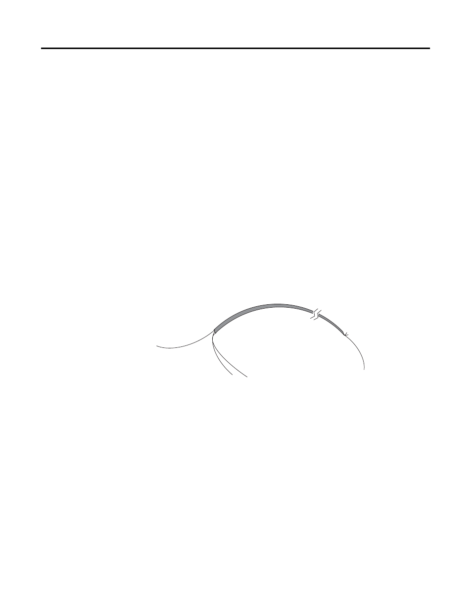
Cable
(Cut foil shield and drain wire.)
Signal Wire
Foil Shield
Drain Wire
Signal Wire
Twist the drain wire and the foil shield together and connect
to earth ground or to the chassis mounting screws.