Rockwell Automation 1746-NO8V SLC 500 8-Point Analog Output Module/ User Manual User Manual
Page 33
Publication 1746-UM026A-EN-P - September 2003
Configuring the Module 4-9
Parameter Set or Clear (configuration bits 7 and 8)
These bits are used to load the values from Data Parameters 1 and 2
into the corresponding feature. Setting these values also enables most
features. If bit 7 is set (1), then the Data Parameter is cleared. If bit 8 is
set (1), the Data Parameter is set for the feature. A configuration error
occurs if both are set to 1 at the same time.
Parameter Options (configuration bits 9 through 11)
These bit settings determine which option will use the data stored in
the output data parameter words. The parameter options are:
•
Set User Scaling Values
•
Set Clamping Values
•
Set Limit Alarm Values
•
Set Ramping/Rate Limiting Values
•
Set Preset Fault Values
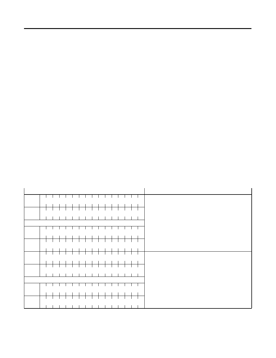
The output data parameters are stored as word pairs for each channel
and use output words 16 through 31. The addressing for this is shown
in the following figure:
Figure 4.2 Output Data Parameter 1 and Output Data Parameter 2
Output Image Words 16 through 31
Function
Output Data Parameter 1
•
Set User Scaling Values: User Scale Low Value
•
Set Clamping Values: User Clamping Low Value
•
Set Limit Alarm Values: Limit Alarm Low Value
•
Set Ramping/ Rate Limiting Values: Ramping Rate
(0-3276.7 millivolts(milliamps)/second)
•
Set Preset fault value
O:e.16
Channel 0
O:e.17
Channel 1
…
O:e.22
Channel 6
O:e.23
Channel 7
Output Data Parameter 2
•
Set User Scaling Values: User Scale High Value
•
Set Clamping Values: User Clamping High Value
•
Set Limit Alarm Values: Limit Alarm High Value
O:e.24
Channel 0
O:e.25
Channel 1
…
O:e.30
Channel 6
O:e.31
Channel 7