Class 1 and class 3 operation, Class 1 and class 3 operation -2 – Rockwell Automation 1746-NO8V SLC 500 8-Point Analog Output Module/ User Manual User Manual
Page 22
Publication 1746-UM026A-EN-P - September 2003
3-2 Preliminary Operating Considerations
Class 1 and Class 3
Operation
The 1746-NO8 analog output modules have multi-class interface
capabilities. Class 1 is the default configuration. The modules can be
configured through the user program for Class 3, which enables
user-defined data scaling and monitoring of channel status words. Use
Class 3 operation whenever possible.
•
Advanced Programming Software (APS) supports Class 3
configuration. After entering the ID code, enter 16 input words
and 32 output words.
•
SLC 500 A.I. Series™ Programming Software supports Class 3
configuration. After entering the ID code, enter 16 input words
and 32 output words.
•
RSLogix 500™, version 1.30 or later, supports Class 3
configuration. After entering the ID code, select Class 3
operation.
•
Earlier versions of RSLogix 500 only support configuration for
Class 1 operation. Contact Rockwell Software for information on
upgrading your software.
•
RSLogix 500 version 6.10 (and later) includes an advanced
configuration wizard to assist in configuring the 1746-NO8
module when Class 3 mode is used.
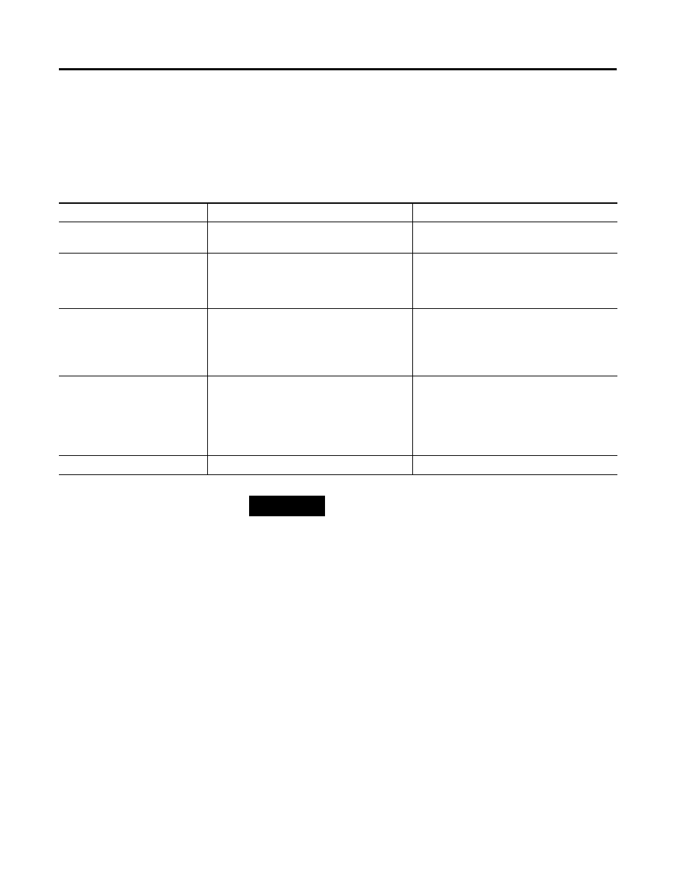
Table 3.2 Class 1 to Class 3 Comparison
Configuration
Class 1
Class 3
Compatible SLC Processors
SLC 500 fixed, SLC 5/01, SLC 5/02, SLC 5/03,
SLC 5/04 and SLC 5/05
SLC 5/02, SLC 5/03, SLC 5/04 and
SLC 5/05
Compatible Chassis
local chassis or remote chassis with a 1747-ASB
module (if remote chassis with 1747-ASB, must
use block transfer for configuration and data
retrieval)
local chassis or remote ControlNet chassis with a
1747-ACN(R)15 module
Input Image
(defined as input from the module
to the SLC 500 processor)
The 8-word input image holds the data received
by the module and provides the status
(configuration and operational state) of each
channel.
The 16-word input image holds the data received
by the module and provides the status
(configuration and operational state) of each
channel. It also provides the extended feature set
status and alarming for each channel.
Output Image
(defined as the output from the
SLC 500 processor to the module)
The 8-word output image defines the output
signal level for each channel.
The 32-word output image defines the output
signal level for each channel, module
configuration (channel enable, output range, data
format), and the optional output data parameters
(user-defined scaling, output clamping, limit
alarms, ramping, preset output on fault).
Default
Class 1 is the default on power-up
Class 3 is programmable by user
TIP
Not all programming software supports configuration
for Class 3 operation.