Input image -3, Input image – Rockwell Automation 1746-NO8V SLC 500 8-Point Analog Output Module/ User Manual User Manual
Page 47
Publication 1746-UM026A-EN-P - September 2003
I/O Data and Status Information 5-3
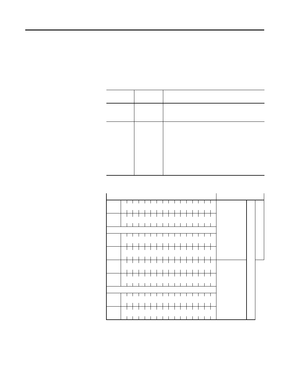
Input Image
The input image (defined as the input from the module to the SLC
processor) provides information to determine various channel
conditions.
Figure 5.2 1746-NO8 Input Image
Table 5.2 1746-NO8 Input Image Operation
Operating
Mode
Input Image
Size
Module Operation
Class 1
8-word
The input data words hold the data received by your
module and provide the status (configuration and
operational state) of each channel.
Class 3
16-word
•
The input data words hold the data received by
your module and provide the status (configuration
and operational state) of each channel.
•
They also provide the extended feature set status
and alarming for each channel.
•
Important - Class 3 features for any particular
channel will only be active if the channel is
enabled. Disabled channels will output 0V (0mA)
no matter what features are configured.
Input Image
Function
Input Status 1
Class 3
Class 1
I:e.0
Channel 0
I:e.1
Channel 1
…
I:e.6
Channel 6
I:e.7
Channel 7
Input Status 2
I:e.8
Channel 0
I:e.9
Channel 1
…
I:e.14
Channel 6
I:e.15
Channel 7