Configuring each output channel, Configuring each output channel -6, Class 1 and class 3 configuration – Rockwell Automation 1746-NO8V SLC 500 8-Point Analog Output Module/ User Manual User Manual
Page 30: Class 3 configuration
Publication 1746-UM026A-EN-P - September 2003
4-6 Configuring the Module
Configuring Each Output
Channel
Class 1 and Class 3 Configuration
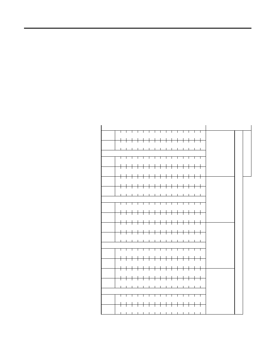
Output words 0 through 7 (addresses O:e.0 through O:e.7) hold the
output data for channels 0 through 7 respectively.
Class 3 Configuration
After installing the module, you must configure each channel by
setting bit values in each configuration word. Output words 8 through
15 (addresses O:e.8 through O:e.15) configure channels 0 through 7
respectively.
Figure 4.1 1746-NO8 Output Addressing
Output Image
Function
Output Data
Class 3
Class 1
O:e.0
Channel 0
O:e.1
Channel 1
…
O:e.6
Channel 6
O:e.7
Channel 7
Configuration
Output
O:e.8
Channel 0
O:e.9
Channel 1
…
O:e.14
Channel 6
O:e.15
Channel 7
Output Data
Parameter 1
O:e.16
Channel 0
O:e.17
Channel 1
…
O:e.22
Channel 6
O:e.23
Channel 7
Output Data
Parameter 2
O:e.24
Channel 0
O:e.25
Channel 1
…
O:e.30
Channel 6
O:e.31
Channel 7