Rockwell Automation 1756-CFM ControlLogix Configurable Flowmeter Module User Manual
Page 101
101
Rockwell Automation Publication 1756-UM010B-EN-P - December 2011
Configuring the Configurable Flowmeter Module 101
Sample Configuration for
Totalizer Mode
Prover Function
In the Totalizer Mode Prover function, the CFM module interfaces to a prover
and counts pulses using a Flowmeter or positive displacement meter. The
module then scales pulse count to engineering units. The CFM module also
calculates frequency over a user-defined time period.
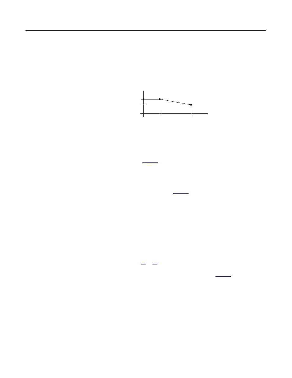
When using totalizer mode (with prover or fill function), you may apply a
K-factor as a function of frequency, as shown below.
This section offers a sample configuration to configure your CFM module for
totalizer mode prover function. In this configuration, channel 0 is configured
and channel 1 is left unused. For a detailed explanation of the features available
in this mode, see
.
Follow the steps below to configure your CFM module for totalizer mode
prover function.
1. Create a new module, see
2. Set all communications options, including:
name
communication format
slot number
minor revision
electronic keying
RPI - For this application, the minimum RPI = 50 ms
See pages
81
.
3. Access the module tags via the Tag Editor, see
.
K-Factor
Frequency
0
100
150
550
600