Scalar (configuration word 7), Output 0-1 ties (configuration words 8 and 9) – Rockwell Automation 1734-VHSC24 Very High-Speed Counter Modules User Manual User Manual
Page 39
Publication 1734-UM003B-EN-P - August 2000
Very High-Speed Counter Module Input and Output Data 3-9
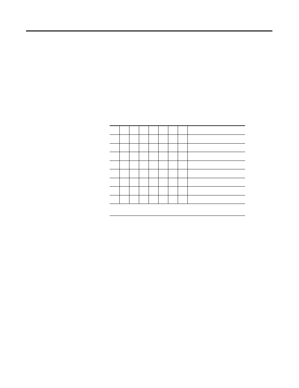
Scalar (Configuration Word 7)
This byte scales the Z signal in the period/rate [5] and continuous/rate
[6] configurations. If the filter is applied, then the filtered Z is scaled.
Only one bit of the scalar should be set. Selecting a scalar causes
accumulated counts to be adjusted accordingly. Selecting a scalar of
128 increases the accumulated count by 128 after 128 Z pulses are
received. We highly recommend that anytime Z is scaled (divide by 2,
4, 8...), the Z input should be filtered; otherwise, noise could cause
erroneous frequency readings.
Scalar Selection
Output 0-1 Ties (Configuration Words 8 and 9)
The bits in these two bytes connect the specified output to the
appropriate compare window. There are 4 windows associated with
the counter. Each output may be connected to any number of
windows, from 1 to all 4. The bits are defined as follows:
T0 -
Tie Output to 1st Compare Window (also the PWM signal in
PWM [3] configuration)
T1 -
Tie Output to 2
nd
Compare Window
T2 -
Tie Output to 3
rd
Compare Window
T3 -
Tie Output to 4
th
Compare Window
07
06
05
04
03
02
01
00
Scalar
1
0
0
0
0
0
0
0
1
Z - F
min
= 0.149 Hz
0
0
0
0
0
0
1
0
Z/2 - F
min
= 0.298 Hz
0
0
0
0
0
1
0
0
Z/4 - F
min
= 0.596 Hz
0
0
0
0
1
0
0
0
Z/8 - F
min
= 1.192 Hz
0
0
0
1
0
0
0
0
Z/16 - F
min
= 2.384 Hz
0
0
1
0
0
0
0
0
Z/32 - F
min
= 4.768 Hz
0
1
0
0
0
0
0
0
Z/64 - F
min
= 9.537 Hz
1
0
0
0
0
0
0
0
Z/128 - F
min
= 19.073 Hz
1 Where F
min
indicates the frequency at which the zero frequency detect is asserted
due to counter overflow.