Encoder modes, Example of counter mode – Rockwell Automation 1734-VHSC24 Very High-Speed Counter Modules User Manual User Manual
Page 13
Publication 1734-UM003B-EN-P - August 2005
About the Modules 1-3
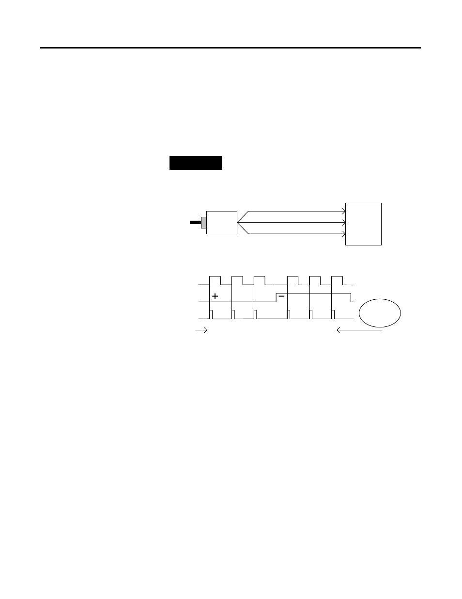
Channel A input is used as the counting pulse while channel B is used
to determine the direction.
[B = High, Count = Down; B = Low or floating (not connected), Count
= Up]
The Channel B input may be tied high or low for unidirectional
counting, or toggled for bidirectional counting.
EXAMPLE
Example of Counter Mode
Encoder Modes
The encoder mode reads incoming pulses and returns a binary
number (0 - 16,777,215
max
) to the POINTBus. The encoder mode
only accepts two-phase quadrature inputs. The module senses the
relationship between the 2 phases, and counts up or down
accordingly.
There are two basic encoder types, absolute and incremental. A
single-output incremental encoder is called a tachometer encoder. A
dual channel incremental encoder with one channel leading the other
by 90
° is called a quadrature encoder.
A system using a quadrature encoder may include an optional zero
pulse, or index, serving as a reference mark for system reset. The
principal disadvantage of a system using incremental encoders is that
a power interruption causes the loss of position reference, so a system
must be reinitialized or returned to a known zero position.
A Input
B Direction
Z (Store Count)
Single Phase Pulse Generator
1734-VHSC
Input A
Input B
1
2
3
A Input
B Input
Count
(Gate / Reset )
2
1
0
Count Up
Count Down
Input Z
0
Outputs
Updated
Continuously