What this chapter contains, Data table, Chapter – Rockwell Automation 1734-VHSC24 Very High-Speed Counter Modules User Manual User Manual
Page 31
1
Publication 1734-UM003B-EN-P - August 2000
Chapter
3
Very High-Speed Counter Module Input and
Output Data
What This Chapter Contains
In this chapter, you learn about the input and output data table of
your 1734-VHSC24 and 1734-VHSC5 Modules.
Data Table
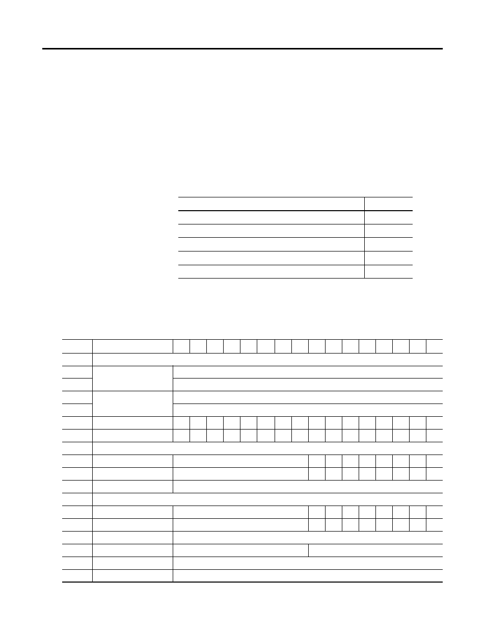
The following table shows the complete format of the input and
output data.
For More Information About
See Page
Detailed Description of Data Table Information
Communicating Real Time Information
15
14
13
12
11
10
09
08
07
06
05
04
03
02
01
0
Input Information
Present Channel Data
32-bit Value of the present counter state
Stored Channel Data
32-bit value of the stored/accumulated count
Status
PE
EF
NR
0
FS
FS
OS
OS
0
ZS
BS
AS
C1
C0
ZD
0
Programming Error Code
PE
0
0
0
0
E10
E9
E8
E7
E6
E5
E4
E3
E2
E1
E0
Output Information
Counter Control
0
0
0
0
0
VR
CP
CR
Output Control
DS
ES
OE
FO
DS
ES
OE
FO
PWM Value
16-bit decimal value with range from 0-9500 (0-95.00%)
Configuration Information
Counter Configuration
ZI
MD
MD
MD
CF
CF
CF
CF
Filter Selection
0
ZF
BF
AF
FS
FS
FS
FS
Decimal Position
8-bit value used to modify the present channel data display
Active Output Assembly
Assembly number (0, 105 or 106)
Time Base/PWM Period
16-bit value used to set the time base or PWM period
Gate Interval
8-bit value used to set the gate interval