Rate measurement mode, Pulse width modulation (pwm) mode – Rockwell Automation 1734-VHSC24 Very High-Speed Counter Modules User Manual User Manual
Page 18
Publication 1734-UM003B-EN-P - August 2005
1-8 About the Modules
Rate Measurement Mode
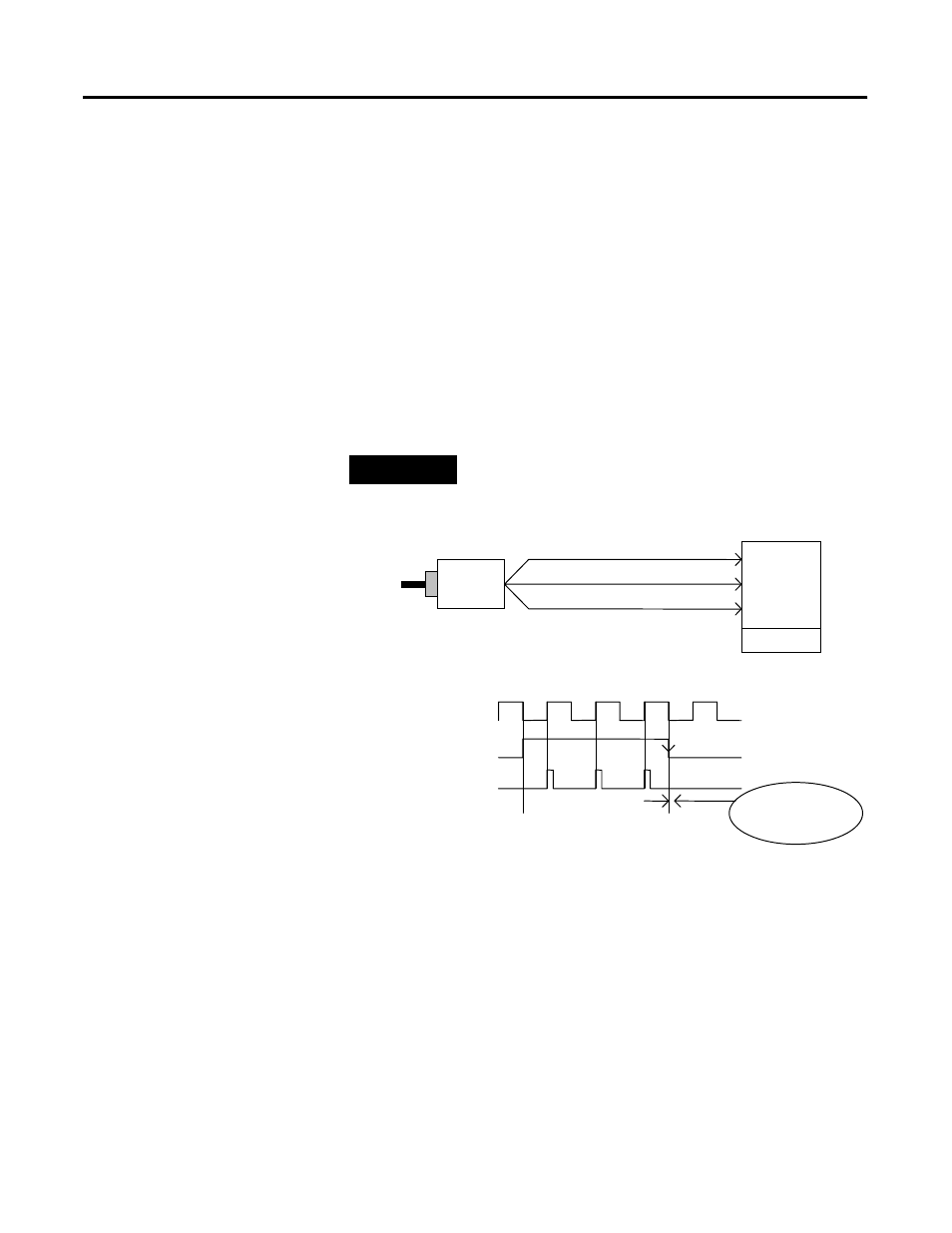
The Rate Measurement mode determines the frequency and total
number of input pulses over a user-specified sample period. At the
end of the interval, the module returns a value representing the
sampled number of pulses and a value indicating the incoming
frequency.
When you update the count and frequency, you check any associated
outputs against their associated presets. Frequency is calculated by
dividing the accumulated count by the user-selected time period, and
is returned in the read data. Allowable time periods are 10 ms to 3 s in
10 ms increments, with a default value of 1 s. Note that a 0 time
period is equivalent to the 1 s default.
EXAMPLE
Example of Rate Measurement Mode
Pulse Width Modulation (PWM) Mode
The Pulse Width Modulation mode uses the counter to generate a
continuous rolling sequence of numbers. The real-time PWM value
written to the module is converted to a window edge so that a
variable duty-cycle signal can be generated. The counter resets to zero
based upon the PWM period programmed into the module. Any
output tied to Window 0 transmits the PWM signal.
A Input
B ( Not Used )
Encoder/Pulse Generator
1734-VHSC
Input A
Input B
A Input ( Pulse )
Internal Sampling Gate
(Gate / Reset )
Input Z
Z ( Not Used )
User Selectable Sample Period,
If Sample Period is 50ms, and Count = 3, then Frequency = 3 /50ms = 60Hz
Accumulated Count
1
Time Base
2
3
Frequency Calculated,
Outputs Updated Here
10ms to 2s in 10ms increments.