Period/rate mode, X4 multiplying encoder mode, Example of period/rate mode – Rockwell Automation 1734-VHSC24 Very High-Speed Counter Modules User Manual User Manual
Page 15
Publication 1734-UM003B-EN-P - August 2005
About the Modules 1-5
X4 Multiplying Encoder Mode
Quadrature input signals are used to count on leading and trailing
edges of A and B for a bidirectional count, and channel B is used to
determine the direction.
[ B = leads A, Count = Down; B = follows A, Count = Up ]
Period/Rate Mode
The Period/Rate mode returns an incoming frequency and a total
accumulated count to the POINTBus, by gating an internal 5 MHz
internal clock with an external signal.
This mode determines the frequency and total number of input pulses
by counting the number of internal 5MHz clock pulses over a
user-specified number of input signal pulses. At the end of the
specified number of pulses, the module returns the frequency
(0 - 1 MHz). When the frequency is updated, both outputs are
checked against their associated presets.
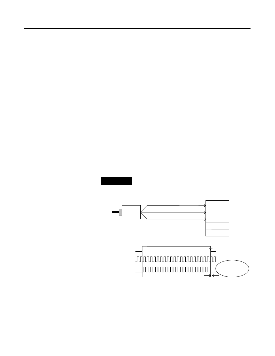
EXAMPLE
Example of Period/Rate Mode
A ( Not Used )
B ( Not Used )
Encoder / Pulse Generator
1734-VHSC
Input A
Input B
Z Input ( Pulse )
5 MHz Internal
(Gate / Reset )
Input Z
Z
Accumulated Count
1
Scalar
5 MHz Clk
Sampling Clock
Assumes symmetrical pulse, 50% duty cycle, so Period = Sample Time On X 2 {On & Off}
10
20
Frequency = 1 / Period If Count = 20, Scalar = 1, and Clock Period = ( 1 / 5 MHz )
Frequency = 1 / [ ( 20 / 1 ) X ( 1 / 5 MHz ) X 2 ] = 125 kHz
Frequency & Outputs
Updated Here