Controller status leds – Rockwell Automation 440C Guardmaster 440C-CR30 Configurable Safety Relay User Manual User Manual
Page 93
Rockwell Automation Publication 440C-UM001C-EN-P - November 2014
93
LEDs
Chapter 13
In the previous example:
a. Input LED 1 is monitoring a terminal status. In this case, it is
monitoring terminal 01. When the signal to terminal 1 is HI, the LED
is on. When the signal to terminal 1 is LO, the LED is off. If this were a
single channel input, then the LED provides all information that we
need to know about the input.
b. Input LED 2 is monitoring safety monitoring function 1. If the LED is
on, then we know that all inputs are satisfied for whatever function (for
example, dual channel input, muting, or two-hand control) is being
monitored.
c. Output LED 3 is monitoring the status of a Safety Output Function. In
this case, SOF 1 is being monitored. If SOF 1 is driving four outputs
(two safety, one diagnostic, and one Modbus), we expect all four
outputs to be HI when LED 3 is on.
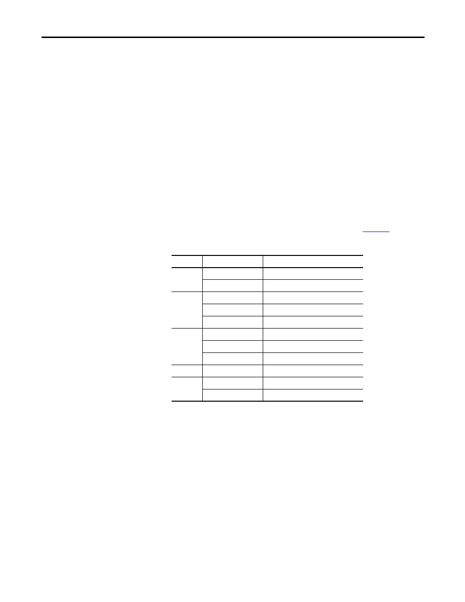
Controller Status LEDs
The CR30 has five module status LEDs that are described in
.
Table 15 - Status LEDs
LED
Color
Indicates
POWER
Off
No input power or power error condition
Green
Power on
RUN
Off
Program mode
Green
Run mode
Flashing Green [2 Hz]
Application is running but not verified
FAULT
Off
No fault detected
Red Flashing [2 Hz]
Application fault detected, recoverable
Red
Controller hardware faulted, non-recoverable
LOCK
Off
Not used
COM
Off
No communications
Green
Communications by serial port or USB