Output pulse testing – Rockwell Automation 440C Guardmaster 440C-CR30 Configurable Safety Relay User Manual User Manual
Page 37
Rockwell Automation Publication 440C-UM001C-EN-P - November 2014
37
Pulse Testing
Chapter 5
The purpose of the test pulses is to detect short circuits from the input signal to
24V DC, 24V common, and shorts from one input signal to another input signal.
If one input signal is assigned to Test Pulse A and another signal is assigned to
Test Pulse B (or C), then a short circuit from one input to the other is detected by
the CR30, and the CR30 de-energizes the outputs of those safety functions using
the two inputs. In this example, you cannot select terminal 12 as one test pulse
source and terminal 15 as the second test pulse source, as both of these produce
the “A” pulse.
The CCW automatically prevents the user from selecting two of the same pulses
when dual channel inputs and two test sources are selected.
Output Pulse Testing
Internally, the CR30 provides dual channel capability to turn off its safety
outputs. Conceptually, think of this as a main output transistor feeding
individual output transistors. The CR30 repeats a test process where it tests the
main transistor twice and then sequentially tests each individual output twice.
After successful completion of the tests, the CR30 repeats the test sequence.
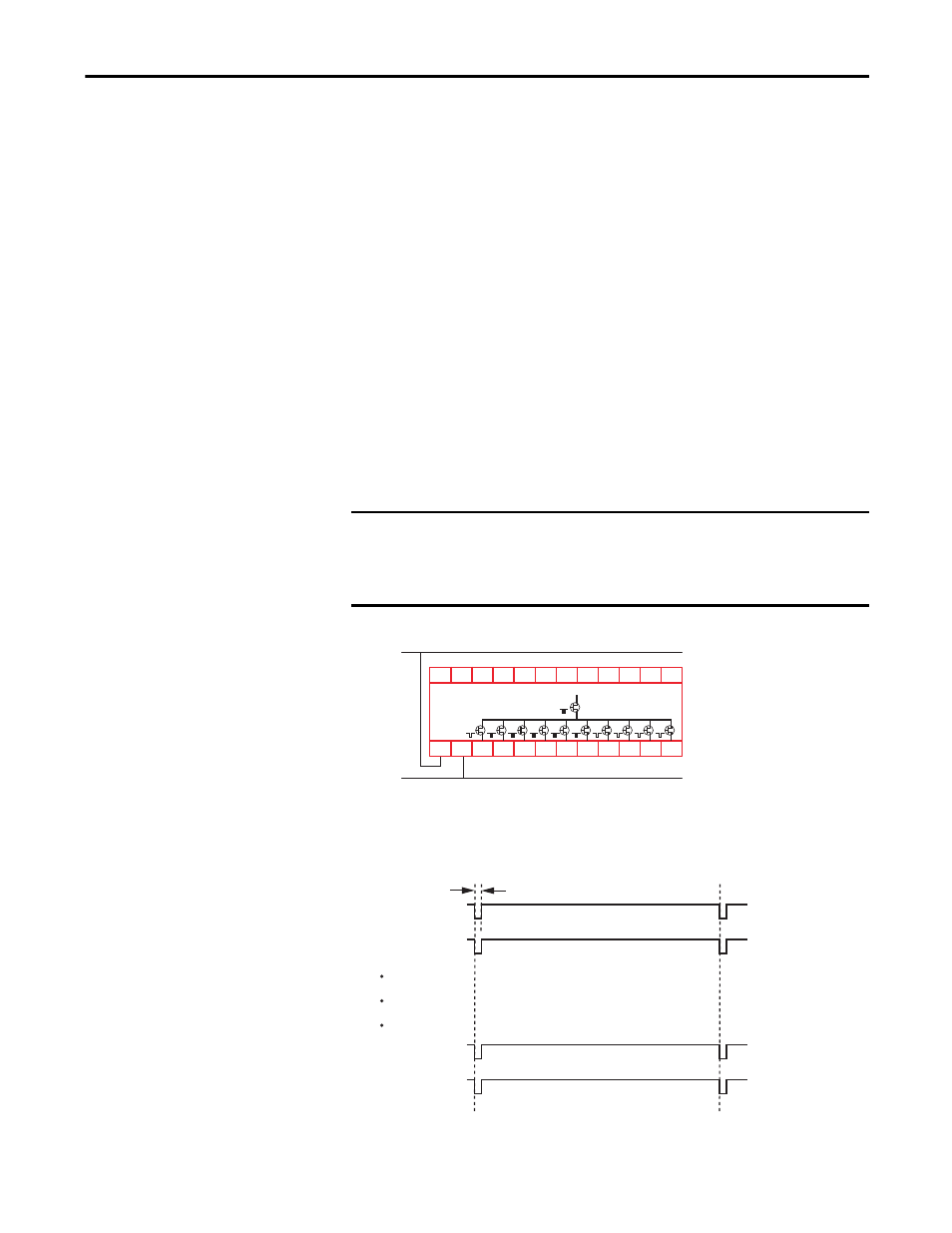
Figure 20 - Output Pulse Testing
When the main transistor is tested, a 50 μs test pulse appears simultaneously on
all outputs. The main transistor is tested again 125 ms later.
Figure 21 - Main Transistor Test
IMPORTANT
Safety systems requiring a Category 4 structure per ISO13849-1 and SIL 3
rating per IEC61508 must use pulse testing for the dual channel outputs. Pulse
testing for Category 3, 2, and 1 structures and SIL 2 and 1 ratings is
recommended.
+24V DC
24V Com
05
CR30
02
01
00
03 04
A1
15
20 21
16
06
18
A2
07
19
08
10 11
12 13 14
09
17
Main Transistor
Terminal 13
Terminal 12
24V
0V
24V
0V
Terminal 20
Terminal 21
24V
0V
24V
0V
0
125ms
50μs