Power cycling – Rockwell Automation 440C Guardmaster 440C-CR30 Configurable Safety Relay User Manual User Manual
Page 24
24
Rockwell Automation Publication 440C-UM001C-EN-P - November 2014
Chapter 3
Power, Ground, and Wiring
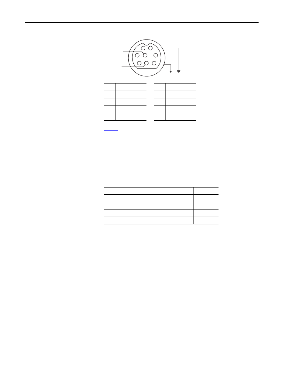
Figure 9 - Pinouts
shows a recommended list of cables for the serial connection between the
CR30 and other Allen-Bradley products. They may also be suitable for third-
party products.
DIN connectors were originally standardized by the Deutsches Institut für
Normung (DIN), the German national standards organization. Many variations
of this connector exist. To help ensure compatibility, select a cable from the
following table.
Table 3 - Cables
The CR30 is categorized as Data Communications Equipment (DCE). The
PanelView HMI's are Data Terminal Equipment (DTE). This is important when
point-to-point wiring connections are made. When DTE communicates with
DCE, the connections are pin x to pin x. When DTE communicates with other
DTE, a cross over is required (for example, TxD must be connected to RxD).
Power Cycling
The state of the CR30 upon power-up depends on its state when power was
turned off. The Run LED indicates the state of the CR30.
1.
Program Mode (RUN LED off )
The CR30 is in program mode upon power-up.
2.
Run Mode with Program Not Verified (RUN LED flashing)
The CR30 returns to Run mode. Run mode without verification is good
for only 24 hours on continuous running.
3.
Run Mode with Program Verified (RUN LED solid green)
The CR30 returns to Run mode with no limitation on the run duration.
Pin
RS-232 Example
Pin
RS-232 Example
1
RS-485 (not used)
5
DCD (not used)
2
GND
6
CTS (not used)
3
RTS (not used)
7
TxD
4
RxD
8
RS-485 (not used)
Cat. No.
Description
Length
1761-CBL-AM00
8-pin Mini DIN to 8-pin Mini DIN
0.5 m (1.5 ft)
1761-CBL-HM02
8-pin Mini DIN to 8-pin Mini DIN
2 m (6.5 ft)
1761-CBL-AP00
8-pin Mini DIN to 9-pin D-shell
0.5 m (1.5 ft)
1761-CBL-PM02
8-pin Mini DIN to 9-pin D-shell
2 m (6.5 ft)
2
1
3
4
6
8
7
5
24V Common
Receive
Transmit