Restart – Rockwell Automation 440C Guardmaster 440C-CR30 Configurable Safety Relay User Manual User Manual
Page 61
Rockwell Automation Publication 440C-UM001C-EN-P - November 2014
61
Safety Monitoring Functions
Chapter 9
Figure 57 - Wiring Connection for a Reset Signal to Terminal 00
The reset block works with one or more output blocks. When an output block
requires a manual reset, the CCW shows all available reset inputs that can be
used.
Restart
The restart function works with an AND or OR logic block in Logic Level A and
Logic Level B. When all inputs are satisfied, exercising the restart input causes the
restart function go be effective. If the Restart function is already effective, the
Restart input has no affect.
The Restart can only be used with one AND or OR logic block.
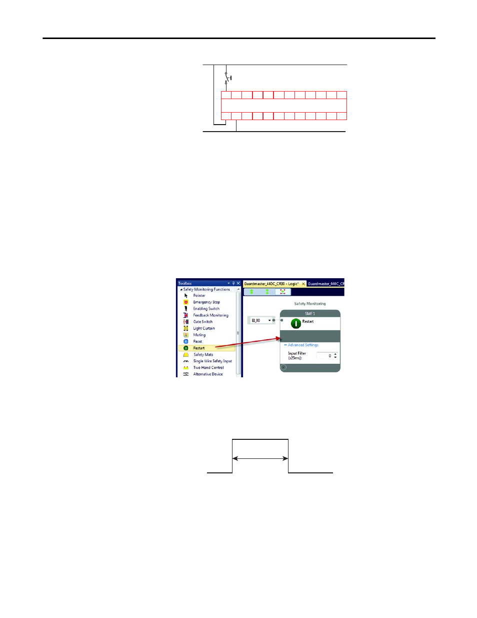
Figure 58 - Restart Function Block
The Restart Function requires a leading edge and trailing edge within a specific
time frame. The pulse width must be between 250…3000 ms. If the pulse width is
too short or too long, the Restart function will not be executed.
Figure 59 - Restart Timing
The available input selections for the Restart are:
•
EI_00…EI_11 (embedded input terminals 00…11)
•
MP_12…MP_17 (multi-purpose terminals 12…17)
•
P1_00…P1_03 (plug-in 1 terminals 00…03)
•
P2_00…P2_03 (plug-in 2 terminals 00…03)
•
SP_00…SP_15 (Modbus inputs 00…15)
+24V DC
Reset
24V Com
05
CR30
02
01
00
03 04
A1
15
20 21
16
06
18
A2
07
19
08
10 11
12 13 14
09
17
+24V DC
24V Com
250ms to
3000 ms