Rockwell Automation LPM20 Liquid-Cooled AC Drive with High Performance Drive Control User Manual
Page 39
Installation/Wiring
1-27
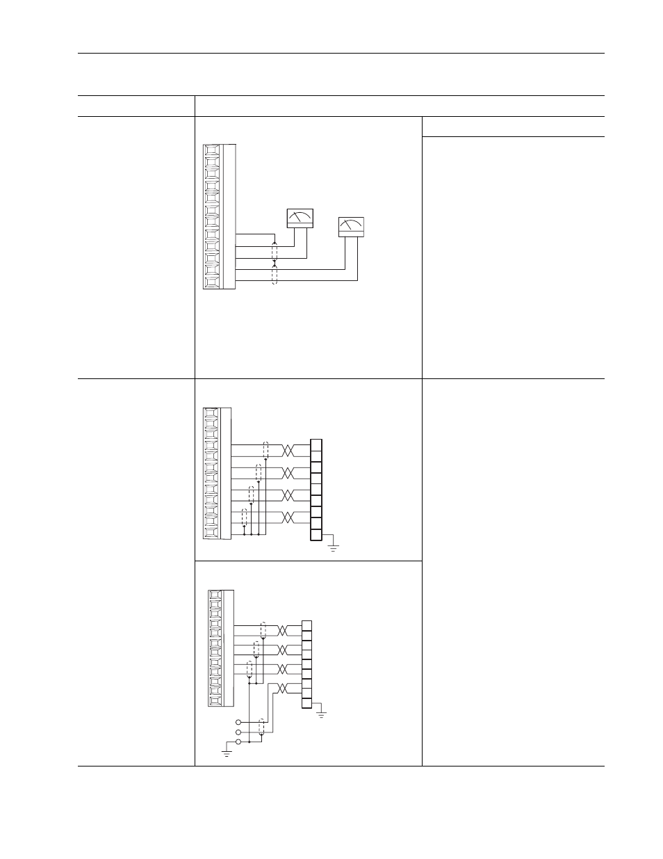
Analog Output
+/- 10V dc
Used to drive analog meters
displaying speed and current.
0-10V Analog Output
Required Parameter Changes
Using Analog Output 1 (-10V to +10V) to meter
Motor RPM and direction:
• Send the data to the Analog Output Parameter
833 [Anlg Out1 Real], the destination, linked to
Parameter 71 [Filtered SpdFdbk], the source.
• Scale the Output to the source parameter.
Example: Parameter 835 [Anlg Out1 Scale] =
175 (where Parameter 4 [Motor NP RPM] 1750
is divided by 10V output).
Using Analog Output 2 (-10V to +10V) to meter
Motor current:
• Send the data to the Analog Output Parameter
840 [Anlg Out2 Real], the destination, linked to
Parameter 308 [Output Current], the source.
• Scale the Output to the source parameter.
Example: Parameter 822 [Anlg Out2 Scale] = xx
(where Parameter 2 [Motor NP FLA] is divided
by 10V output).
Primary Encoder Interface -
Supports 5V dc/12 V dc
differential encoders with
internal power supply.
Primary Encoder - Internal Supply
Using Encoder 0 as speed feedback:
• Set Parameter 222 [Motor Fdbk Sel Pri] to a
value of 0 (Encoder 0 = default), so the drive will
use this encoder as the primary motor speed
feedback device.
• Set the value of Parameter 232 [Encoder 0
PPR] to match the installed encoder’s resolution
(Pulses per Revolution).
Primary Encoder - External Supply
Figure 1.10 TB1 Terminals — Analog Wiring Examples (Continued)
Input/Output
Connection Example
-
+
-
+
1
2
3
4
5
6
7
8
9
12
10
11
A-
-
+
Z-
Z
B-
B
A
Encoder
The Z channel is not
required in typical
applications
13
14
15
16
17
18
19
20
21
22
23
24
A-
-
+
Z-
Z
B-
B
A
Encoder
The Z channel is not
required in typical
applications
Power +V
Common -V
Shield
13
14
15
16
17
18
19
20
21
22
23
24