Rockwell Automation LPM20 Liquid-Cooled AC Drive with High Performance Drive Control User Manual
Page 21
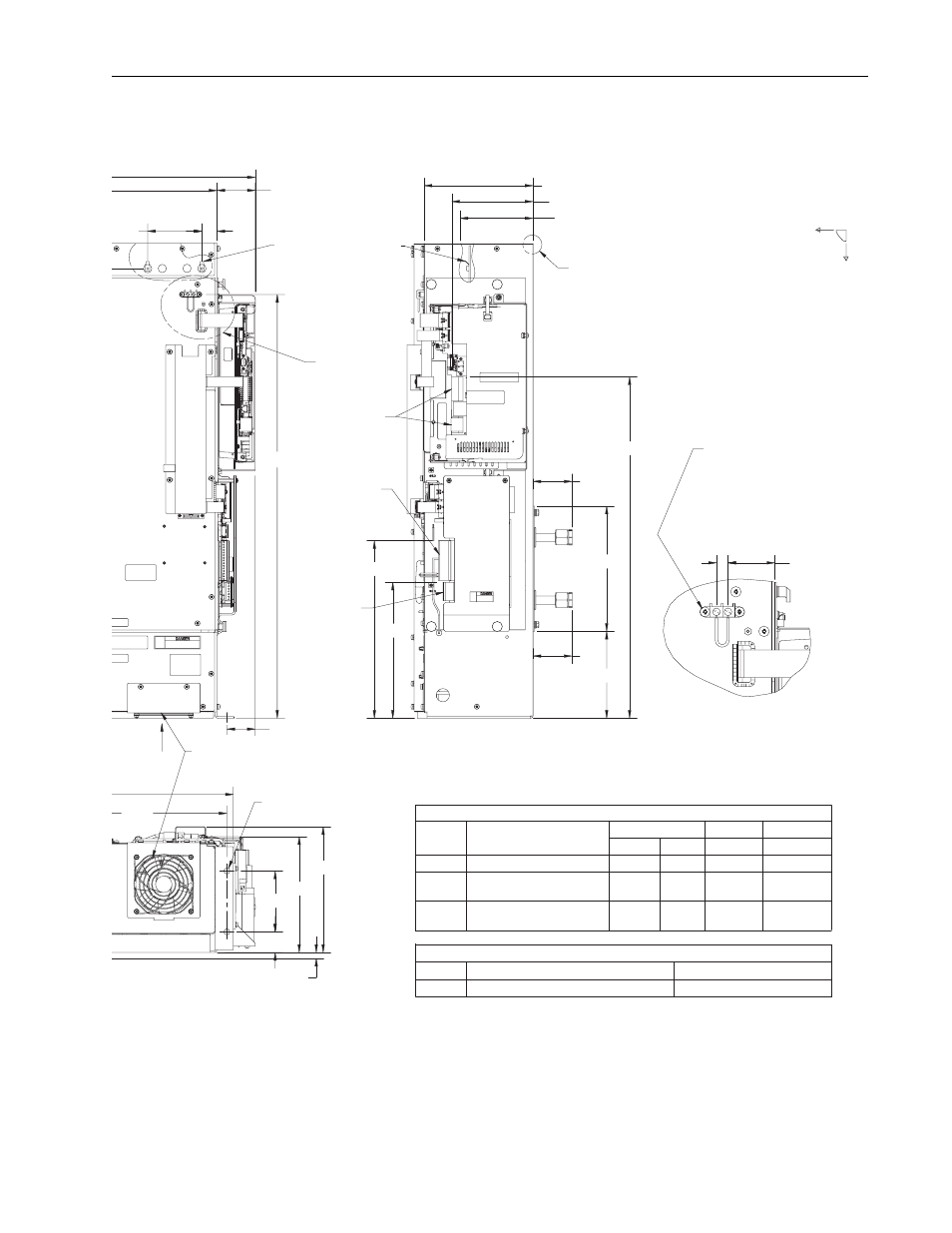
Installation/Wiring
1-9
2.15
10.32
13.47
9.56
8.80
2.92
25.90
4.12
1.15
4.63
Ø.453 (4)-PL. See Note 1
1.56
17.50
32.16
6.60
9.50
1.78
0.44
0.44
2.96
2.96
FIELD CONTROL WIRING
Wire Size Strip Length
Name
Reference
[N-M]
[IN-LBF]
[AWG]
[Inch]
A33
#6-32 Screw
0.90
8
24 to 10
Screwdriver Blade:
0.032" Thk. x 0.125" Wide
Screwdriver Blade:
0.017" Thk. x 0.094" Wide
0.79
7
26 to 12
0.31
0.22
1.9
28 to 16
0.25
A1-P1 LINE SYNC. ASS'Y HARNESS CONNECTOR
A1-P1
MATE
Cooling Fan Requires 1.13" Minimum
Unobstructed Space Below Fan
DC
Neg (-)
DC
Pos (+)
DC Bus Measurement
Points on Laminated
Bus Ass'y 0.25" x 0.032"
Male Faston. Accessible
by Removal of Top Cover.
AIRFLOW
SEE DETAIL
GATE KILL
A22-TB1 & TB2
Main Control Ass'y
Terminal Blocks
A11-P2 Voltage
Feedback
Resistor Ass'y
Terminal
Block 7-Pos.
A12-P1 Active
Converter Control
Ass'y Terminal
Block 15-Pos.
BOTTOM VIEW
RIGHT SIDE VIEW
SEE DETAIL COG
DETAIL COG
IN
OUT
Y
X
2 1
DETAIL GATE KILL
SCALE 5:8
A32
A31
A33
A33
Torque
−
A12-P1
A11-P2
A22-TB1
A22-TB2
Pin Housing, AMP P/N 172171-1
Socket Housing, AMP P/N 172163-1
Socket, AMP P/N 770903-3
Pin, AMP P/N 770904-3
A33 Gate Kill
2-Pos. Terminal Block
With #6-32 Phillips/Slotted
Screws. Accepts #6 Stud Size
Spade Tongue Terminal.
Max. Width is 0.37".
8.27 (A33)
6.17 (A22-TB1 & TB2)
5.54 (DC Bus Measurement Points)
CENTER OF GRAVITY:
X = 17.5"
Y = 3.1"
Z = 7.4" (into Plane
of Drawing)
WEIGHT:
162 LBS.
SCALE 5:16